Mitsubishi Electric MU-GF20VA Service Manual
Outdoor unit
Hide thumbs
Also See for MU-GF20VA:
- Operating instructions manual (29 pages) ,
- Installation manual (5 pages)
Advertisement
Table of Contents
- 1 Table of Contents
- 2 Outdoor Unit
- 3 Service Manual
- 4 Revision a
- 5 Technical Changes
- 6 Part Names and Functions
- 7 Specification
- 8 Noise Criteria Curves
- 9 Outlines and Dimensions
- 10 Wiring Diagram
- 11 Refrigerant System Diagram
- 12 Performance Curves
- 13 Troubleshooting
- 14 Disassembly Instructions
- Download this manual
SPLIT-TYPE AIR CONDITIONERS
OUTDOOR UNIT
SERVICE MANUAL
Models
MU-GF20VA
MU-GF25VA
MU-GF35VA
MU-GF50VA -
MU-GF60VA -
MU-GF80VA -
MU-GF20/25/35VA
NOTE:
RoHS compliant products have <G> mark on
the spec name plate.
-
E1
-
E1
-
E1
E1
E1
E1
CONTENTS
1. TECHNICAL CHANGES ···································
2. PART NAMES AND FUNCTIONS ····················· 3
3. SPECIFICATION ················································
4. NOISE CRITERIA CURVES ······························
5. OUTLINES AND DIMENSIONS ························
6. WIRING DIAGRAM ············································
7. REFRIGERANT SYSTEM DIAGRAM ·············· 11
8. PERFORMANCE CURVES ·····························
9. TROUBLESHOOTING ·····································
10. DISASSEMBLY INSTRUCTIONS ···················· 31
PARTS CATALOG (OBB622)
• MU-GF50VA-
, MU-GF60VA-
E1
MU-GF80VA-
have been added.
E1
Please void OBH622.
No. OBH622
HFC
REVISED EDITION-A
utilized
R410A
Indoor unit service manual
MS-GF•VA Series (OBH621)
and
E1
2
4
5
7
9
14
29
Advertisement
Table of Contents

Related Manuals for Mitsubishi Electric MU-GF20VA


Summary of Contents for Mitsubishi Electric MU-GF20VA
-
Page 1: Table Of Contents
SPLIT-TYPE AIR CONDITIONERS Please void OBH622. OUTDOOR UNIT No. OBH622 SERVICE MANUAL REVISED EDITION-A utilized R410A Models MU-GF20VA MU-GF25VA MU-GF35VA MU-GF50VA - MU-GF60VA - MU-GF80VA - Indoor unit service manual MS-GF•VA Series (OBH621) CONTENTS 1. TECHNICAL CHANGES ···································... -
Page 2: Technical Changes
When the repair or the inspection of the circuit needs to be done without turning off the power, exercise great caution not to touch the live parts. Revision A: • MU-GF50VA- , MU-GF60VA- and MU-GF80VA- have been added. TECHNICAL CHANGES MU-GF20VA - MU-GF25VA - MU-GF35VA - 1. New model MU-GF50VA - MU-GF60VA - MU-GF80VA - 1. New model... -
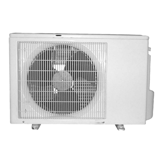
Page 3: Part Names And Functions
PART NAMES AND FUNCTIONS MU-GF20VA MU-GF25VA MU-GF35VA Air inlet (back and side) Piping Drain hose Air outlet Drain outlet MU-GF50VA Air inlet (back and side) Piping Drain hose Air outlet Drain outlet MU-GF60VA MU-GF80VA Air inlet (back and side) Piping... -
Page 4: Specification
SPECIFICATION Outdoor model MU-GF20VA MU-GF25VA MU-GF35VA MU-GF50VA MU-GF60VA MU-GF80VA Function Cooling Single phase Power supply 230 V, 50 Hz Capacity 3.45 4.85 Breaker capacity Running current (Total) 12.5 Power input (Total) 1,120 1,480 2,170 2,780 Power factor (Total) Starting current (Total) 14.5... -
Page 5: Noise Criteria Curves
NOISE CRITERIA CURVES MU-GF20VA MU-GF25VA FUNCTION SPL(dB(A)) LINE FUNCTION SPL(dB(A)) LINE COOLING COOLING NC-70 NC-70 NC-60 NC-60 NC-50 NC-50 NC-40 NC-40 NC-30 NC-30 NC-20 NC-20 NC-10 NC-10 1000 2000 4000 8000 1000 2000 4000 8000 BAND CENTER FREQUENCIES, Hz BAND CENTER FREQUENCIES, Hz... - Page 6 MU-GF50VA MU-GF60VA FUNCTION SPL(dB(A)) LINE FUNCTION SPL(dB(A)) LINE COOLING COOLING NC-70 NC-70 NC-60 NC-60 NC-50 NC-50 NC-40 NC-40 NC-30 NC-30 NC-20 NC-20 NC-10 NC-10 1000 2000 4000 8000 1000 2000 4000 8000 BAND CENTER FREQUENCIES, Hz BAND CENTER FREQUENCIES, Hz MU-GF80VA FUNCTION SPL(dB(A)) LINE...
-
Page 7: Outlines And Dimensions
OUTLINES AND DIMENSIONS MU-GF20VA MU-GF25VA MU-GF35VA Unit: mm REQUIRED SPACE Drain hole ø33 Air in Open two sides of left, right, or rear side. Air in Air out 2 holes 10 x 16 Service panel Liquid refrigerant pipe joint Handle Refrigerant pipe (flared) ø6.35... - Page 8 MU-GF50VA Unit: mm Basically open 100mm or more REQUIRED SPACE without any obstruction in front and on both sides of the unit. Drain hole ø42 Air in Air in Open two sides of left, 2 holes 10x21 right, or rear side. Service panel Air out 22.3...
-
Page 9: Wiring Diagram
WIRING DIAGRAM MU-GF20VA MU-GF25VA MU-GF35VA MU-GF50VA OBH622A... -
Page 10: Obh622A
MU-GF60VA MU-GF80VA OBH622A... -
Page 11: Refrigerant System Diagram
REFRIGERANT SYSTEM DIAGRAM MU-GF20VA MU-GF25VA Unit: mm Refrigerant pipe 9.52 Stop valve (with heat insulator) (with service port) Outdoor heat exchanger Flared connection Strainer Compressor #100 Flared connection Capillary tube Stop valve 3.0 x 1.4 x 900 Refrigerant pipe 6.35... -
Page 12: Obh622A
MU-GF60VA Unit: mm Refrigerant pipe ø 15.88 (with heat insulator) Strainer Stop valve #100 (with service port) Outdoor heat Muffler Flared connection ø38 exchanger Compressor Flared connection Stop valve Capillary tube ø 3.0 × ø 2.0 × 600 Refrigerant pipe ø 6.35 (with heat insulator) Refrigerant flow in cooling MU-GF80VA... -
Page 13: Obh622A
MAX. HEIGHT DIFFERENCE Indoor unit Max. Height Refrigerant Piping difference Max. Length Outdoor unit ADDITIONAL REFRIGERANT CHARGE (R410A: g) MU-GF20VA MU-GF25VA MU-GF35VA Refrigerant piping length (one way) Model Outdoor unit precharged 7.5m MU-GF20VA MU-GF25VA MU-GF35VA 1,100 Calculation: Xg = 20 g/m x (Refrigerant piping length (m) - 7.5) NOTE: Refrigerant piping exceeding 7.5 m requires additional refrigerant charge according to the calculation. -
Page 14: Performance Curves
PERFORMANCE CURVES MU-GF20VA MU-GF25VA MU-GF35VA MU-GF50VA MU-GF60VA MU-GF80VA The standard specifications apply only to the operation of the air conditioner under normal conditions. Since operating condi- tions vary according to the areas where these units are installed, the following information has been provided to clarify the operating characteristics of the air conditioner under the conditions indicated by the performance curve. -
Page 15: Obh622A
Relative humidity (%) Both indoor and outdoor unit are under the same temperature/ humidity condition. Air flow should be set at MAX. Outdoor low pressure MU-GF25VA MU-GF35VA MU-GF20VA (kgf/cm [Gauge])(MPa [Gauge]) (kgf/cm [Gauge])(MPa [Gauge]) (kgf/cm [Gauge])(MPa [Gauge]) Ambient temperature (°C) Ambient temperature (°C) -
Page 16: Obh622A
Outdoor unit current MU-GF25VA MU-GF35VA MU-GF20VA Ambient temperature (°C) Ambient temperature (°C) Ambient temperature (°C) Ambient humidity(%) Ambient humidity(%) Ambient humidity(%) MU-GF60VA MU-GF80VA MU-GF50VA Ambient temperature (°C) Ambient temperature (°C) Ambient temperature (°C) Ambient humidity(%) Ambient humidity(%) Ambient humidity(%) OBH622A... -
Page 17: Obh622A
PERFORMANCE DATA COOL operation a t Rated frequency MU-GF20VA CAPACITY: 2.3 kW SHF: 0.84 INPUT: 710 W OUTDOOR DB (°C) INDOOR INDOOR DB (°C) WB (°C) INPUT INPUT INPUT INPUT 2.70 1.78 0.66 2.59 1.71 0.66 2.48 1.64 0.66 2.39 1.58... -
Page 18: Obh622A
PERFORMANCE DATA COOL operation a t Rated frequency MU-GF20VA CAPACITY: 2.3 kW SHF: 0.84 INPUT: 710 W OUTDOOR DB (°C) INDOOR INDOOR DB (°C) WB (°C) INPUT INPUT INPUT 2.25 1.49 0.66 2.07 1.37 0.66 1.91 1.26 0.66 2.37 1.28 0.54... -
Page 19: Obh622A
PERFORMANCE DATA COOL operation a t Rated frequency MU-GF25VA CAPACITY: 2.5 kW SHF: 0.81 INPUT: 775 W OUTDOOR DB (°C) INDOOR INDOOR DB (°C) WB (°C) INPUT INPUT INPUT INPUT 2.94 1.85 0.63 2.81 1.77 0.63 2.70 1.70 0.63 2.60 1.64 0.63 3.06... -
Page 20: Obh622A
PERFORMANCE DATA COOL operation a t Rated frequency MU-GF25VA CAPACITY: 2.5 kW SHF: 0.81 INPUT: 775 W OUTDOOR DB (°C) INDOOR INDOOR DB (°C) WB (°C) INPUT INPUT INPUT 2.45 1.54 0.63 2.25 1.42 0.63 2.08 1.31 0.63 2.58 1.31 0.51 2.40 1.22... -
Page 21: Obh622A
PERFORMANCE DATA COOL operation a t Rated frequency MU-GF35VA CAPACITY: 3.45 kW SHF: 0.74 INPUT: 1120 W OUTDOOR DB (°C) INDOOR INDOOR DB (°C) WB (°C) INPUT INPUT INPUT INPUT 4.05 2.27 0.56 3.88 2.17 0.56 3.73 2.09 0.56 3.59 2.01 0.56 1030... -
Page 22: Obh622A
PERFORMANCE DATA COOL operation a t Rated frequency MU-GF35VA CAPACITY: 3.45 kW SHF: 0.74 INPUT: 1120 W OUTDOOR DB (°C) INDOOR INDOOR DB (°C) WB (°C) INPUT INPUT INPUT 3.38 1.89 0.56 1098 3.11 1.74 0.56 1165 2.86 1.60 0.56 1210 3.55 1.56... -
Page 23: Obh622A
PERFORMANCE DATA COOL operation a t Rated frequency MU-GF50VA CAPACITY: 4.85 kW SHF: 0.81 INPUT: 1480 W OUTDOOR DB (°C) INDOOR INDOOR DB (°C) WB (°C) INPUT INPUT INPUT INPUT 5.70 3.59 0.63 1184 5.46 3.44 0.63 1243 5.24 3.30 0.63 1302 5.04 3.18 0.63 1362... -
Page 24: Obh622A
PERFORMANCE DATA COOL operation a t Rated frequency MU-GF50VA CAPACITY: 4.85 kW SHF: 0.81 INPUT: 1480 W OUTDOOR DB (°C) INDOOR INDOOR DB (°C) WB (°C) INPUT INPUT INPUT 4.75 2.99 0.63 1450 4.37 2.75 0.63 1539 4.03 2.54 0.63 1598 5.00 2.55 0.51 1510... -
Page 25: Obh622A
PERFORMANCE DATA COOL operation a t Rated frequency MU-GF60VA CAPACITY: 6.4 kW SHF: 0.72 INPUT: 2170 W OUTDOOR DB (°C) INDOOR INDOOR DB (°C) WB (°C) INPUT INPUT INPUT INPUT 7.52 4.06 0.54 1736 7.20 3.89 0.54 1823 6.91 3.73 0.54 1910 6.66 3.59 0.54 1996... -
Page 26: Obh622A
PERFORMANCE DATA COOL operation a t Rated frequency MU-GF60VA CAPACITY: 6.4 kW SHF: 0.72 INPUT: 2170 W OUTDOOR DB (°C) INDOOR INDOOR DB (°C) WB (°C) INPUT INPUT INPUT 6.27 3.39 0.54 2127 5.76 3.11 0.54 2257 5.31 2.87 0.54 2344 6.59 2.77 0.42 2213... -
Page 27: Obh622A
PERFORMANCE DATA COOL operation a t Rated frequency MU-GF80VA CAPACITY: 7.8 kW SHF: 0.67 INPUT: 2780 W OUTDOOR DB (°C) INDOOR INDOOR DB (°C) WB (°C) SHF INPUT SHF INPUT SHF INPUT SHF INPUT 9.17 4.49 0.49 2224 8.78 4.30 0.49 2335 8.42 4.13 0.49 2446 8.11 3.97 0.49 2558 9.56 3.54 0.37 2335... -
Page 28: Obh622A
PERFORMANCE DATA COOL operation a t Rated frequency MU-GF80VA CAPACITY: 7.8 kW SHF: 0.67 INPUT: 2780 W OUTDOOR DB (°C) INDOOR INDOOR DB (°C) WB (°C) INPUT INPUT INPUT 7.64 3.75 0.49 2724 7.02 3.44 0.49 2891 6.47 3.17 0.49 3002 8.03 2.97 0.37 2836... -
Page 29: Troubleshooting
TROUBLESHOOTING MU-GF20VA MU-GF25VA MU-GF35VA MU-GF50VA MU-GF60VA MU-GF80VA 9-1. CAUTIONS ON TROUBLESHOOTING 1. Before troubleshooting, check the following 1) Check the power supply voltage. 2) Check the indoor/outdoor connecting wire for miswiring. 2. Take care of the following during servicing 1) Before servicing the air conditioner, be sure to turn OFF the main unit first with the remote controller, and then after confirming the horizontal vane is closed, turn OFF the breaker and/or disconnect the power plug. -
Page 30: Obh622A
9-3. TROUBLE CRITERION OF MAIN PARTS MU-GF20VA MU-GF25VA MU-GF35VA MU-GF50VA MU-GF60VA MU-GF80VA Part name Check method and criterion Figure Measure the resistance between terminals using a tester. (Temperature: -10 ~ 40°C) Compressor Normal (Ω) INNER MU-GF20VA MU-GF25VA MU-GF35VA PROTECTOR MU-GF20/60VA 3.98 ~ 4.88... -
Page 31: Disassembly Instructions
Locking lever lever. Connector 10-1. MU-GF20VA MU-GF25VA MU-GF35VA NOTE: Turn OFF power supply before disassembly. OPERATING PROCEDURE PHOTOS 1. Removing the cabinet Photo 1 (1) Remove the screw fixing the service panel and service... -
Page 32: Obh622A
OPERATING PROCEDURE PHOTOS Photo 4 2. Removing the electrical parts (1) Remove the top panel, the service panel and the cabinet. Screw of the Compressor (Refer to 1.) relay panel capacitor (C1) (2) Remove the following parts. •Compressor capacitor (C1) •Outdoor fan capacitor (C2) •Terminal block (TB) Terminal... -
Page 33: Obh622A
10-2. MU-GF50VA NOTE: Turn OFF the power supply before disassembly. OPERATING PROCEDURE PHOTOS 1. Removing the cabinet Photo 1 (1) Remove the screw fixing the service panel (2) Pull down the service panel and remove it. Screws of the front panel and motor support (3) Disconnect the indoor/outdoor connecting wire. -
Page 34: Obh622A
OPERATING PROCEDURE PHOTOS 2. Removing the electrical parts Photo 4 Compressor (1) Remove the service panel and the cabinet. (Refer to 1.) contactor (2) Remove the following parts. Outdoor fan (52C) •Compressor capacitor (C1) capacitor •Outdoor fan capacitor (C2) (C2) •Terminal block (TB) •Compressor contactor (52C) Terminal... -
Page 35: Obh622A
OPERATING PROCEDURE PHOTOS Photo 6 4. Removing the compressor (1) Remove the cabinet. (Refer to 1.) Glass (2) Remove the relay panel. Brazed part of the terminal (3) Remove the soundproof felt. discharge pipe (4) Remove the terminal cover. (5) Pull out the lead wires from the glass terminal of the com- pressor. -
Page 36: Obh622A
10-3. MU-GF60VA NOTE: Turn OFF power supply before disassembly. OPERATING PROCEDURE PHOTOS 1. Removing the cabinet (1) Remove the screws of the service panel. Photo 2 (2) Remove the screws of the top panel. Screws of the back panel (3) Remove the screw of the valve cover. Screws of the (4) Remove the service panel. -
Page 37: Obh622A
OPERATING PROCEDURE PHOTOS 3. Removing propeller and the outdoor fan motor Photo 4 Set screws of the (1) Remove the cabinet (Refer to 1.). outdoor fan motor (2) Remove the propeller nut and remove the propeller. NOTE: Loosen the propeller in the rotating direction for removal. When attaching the propeller, align the mark on the propeller and the motor shaft cut section. -
Page 38: Obh622A
10-4. MU-GF80VA NOTE: Turn OFF power supply before disassembly. OPERATING PROCEDURE PHOTOS 1. Removing the cabinet Photo 2 (1) Remove the screws of the service panel. (2) Remove the screws of the top panel. Screws of the back panel (3) Remove the screw of the valve cover. Screws of the (4) Remove the service panel. -
Page 39: Obh622A
OPERATING PROCEDURE PHOTOS 3. Removing propeller and the outdoor fan motor Photo 4 Set screws of the (1) Remove the cabinet (Refer to 1.). outdoor fan motor (2) Remove the propeller nut and remove the propeller. NOTE: Loosen the propeller in the rotating direction for removal. When attaching the propeller, align the mark on the propeller and the motor shaft cut section. - Page 40 HEAD OFFICE: TOKYO BLDG., 2-7-3, MARUNOUCHI, CHIYODA-KU, TOKYO 100-8310, JAPAN © Copyright 2012 MITSUBISHI ELECTRIC CORPORATION Distributed in Feb. 2013. No. OBH622 REVISED EDITION-A Distributed in Oct. 2012. No. OBH622 New publication, effective Feb. 2013 Made in Japan Specifications are subject to change without notice.
Need help?
Do you have a question about the MU-GF20VA and is the answer not in the manual?
Questions and answers