Sign In
Upload
Manuals
Brands
ABB Manuals
DC Drives
ACH180
ABB ACH180 Manuals
Manuals and User Guides for ABB ACH180. We have
4
ABB ACH180 manuals available for free PDF download: Hardware Manual, User Manual, Quick Installation And Start-Up Manual
ABB ACH180 Hardware Manual (182 pages)
DRIVES FOR HVAC
Brand:
ABB
| Category:
DC Drives
| Size: 63.05 MB
Table of Contents
Table of Contents
5
1 Safety Instructions
13
Contents of this Chapter
13
Use of Warnings and Notes
13
General Safety in Installation, Start-Up and Maintenance
14
Electrical Safety in Installation, Start-Up and Maintenance
16
Electrical Safety Precautions
16
Additional Instructions and Notes
17
Printed Circuit Boards
17
Grounding
18
General Safety in Operation
19
Additional Instructions for Permanent Magnet Motor Drives
19
Safety in Installation, Start-Up, Maintenance
19
Safety in Operation
20
2 Introduction
21
Contents of this Chapter
21
Applicability
21
Target Audience
21
Categorization by Frame Size
21
Quick Installation and Commissioning Flowchart
22
Terms and Abbreviations
23
Related Documents
23
3 Operation Principle and Hardware Description
25
Contents of this Chapter
25
Operation Principle
25
Simplified Main Circuit Diagram
26
Layout
27
Frame Sizes R0
27
Frame R2
28
Frame R3
29
Frame R4
30
Control Connections
31
Control Panel Options
31
Drive Labels
32
Model Information Label
32
Type Designation Label
32
Type Designation Key
33
Integrated Control Panel
33
Home View
35
Status Icon
35
Message View
35
Options View
36
Menu
36
4 Mechanical Installation
37
Contents of this Chapter
37
Installation Alternatives
37
Examining the Installation Site
38
Required Tools
38
Unpacking the Delivery
39
Installing the Drive
40
To Install the Drive with Screws
40
To Install the Drive to a DIN Installation Rail
42
5 Guidelines for Planning the Electrical Installation
43
Contents of this Chapter
43
Limitation of Liability
43
North America
43
Selecting the Main Supply Disconnecting Device
43
Selecting the Main Contactor
44
Checking the Compatibility of the Motor and Drive
44
Selecting the Power Cables
44
General Guidelines
44
Typical Power Cable Sizes
45
Power Cable Types
45
Preferred Power Cable Types
45
Alternate Power Cable Types
46
Not Allowed Power Cable Types
47
Additional Guidelines - North America
47
Metal Conduit
48
Power Cable Shield
48
Grounding Requirements
49
Additional Grounding Requirements - IEC
50
Additional Grounding Requirements - UL (NEC)
51
Selecting the Control Cables
51
Shielding
51
Signals in Separate Cables
51
Signals that Can be Run in the same Cable
51
Relay Cable
52
Control Panel to Drive Cable
52
PC Tool Cable
52
Routing the Cables
52
General Guidelines - IEC
52
General Guidelines - North America
53
Continuous Motor Cable Shield/Conduit and Metal Enclosure for Equipment on the Motor Cable
54
Separate Control Cable Ducts
55
Implementing Short-Circuit and Thermal Overload Protection
55
Protecting the Drive and Input Power Cable in Short-Circuits
55
Protecting the Motor and Motor Cable in Short-Circuits
55
Protecting the Drive, and the Input Power and Motor Cables against Thermal Overload
56
Protecting the Motor against Thermal Overload
56
Protecting the Motor against Overload Without Thermal Model or Temperature Sensors
56
Implementing a Motor Temperature Sensor Connection
57
Protecting the Drive against Ground Faults
57
Residual Current Device Compatibility
57
Implementing the Emergency Stop Function
57
Implementing the Safe Torque off Function
58
Implementing the Control of a Contactor between Drive and Motor
58
Protecting the Contacts of Relay Outputs
58
6 Electrical Installation
61
Contents of this Chapter
61
Required Tools
61
Measuring the Insulation
62
Measuring the Insulation Resistance of the Drive
62
Measuring the Insulation Resistance of the Input Power Cable
62
Measuring the Insulation Resistance of the Motor and Motor Cable
62
Measuring the Insulation Resistance of the Brake Resistor Circuit
63
Grounding System Compatibility Check
63
EMC Filter
63
When to Disconnect the EMC Filter
64
Disconnecting the EMC Filter
65
Guidelines for Installing the Drive to a TT System
65
Identifying the Grounding System of the Electrical Power Network
66
Connecting the Power Cables - IEC (Shielded Cables)
67
Connection Diagram
67
Connection Procedure
68
Connecting the Power Cables - North America (Wiring in Conduits)
71
Connection Diagram
71
Connection Procedure
72
Connecting the Control Cables
73
Default I/O Connection Diagram (HVAC Default)
73
Control Cable Connection Procedure
74
Additional Information on the Control Connections
76
Connecting an Interposing Relay to DO
76
Connecting EIA-485 Fieldbus Cable to the Drive
76
PNP Configuration for Digital Inputs
78
NPN Configuration for Digital Inputs
78
Connection Examples of Two-Wire and Three-Wire Sensors
79
Safe Torque off
79
Connecting a PC
79
CCA-01 Connection
80
7 Installation Checklist
81
Contents of this Chapter
81
Checklist
81
8 Maintenance
85
Contents of this Chapter
85
Maintenance Intervals
85
Description of Symbols
85
Recommended Maintenance Intervals after Start-Up
86
Cleaning the Heatsink
87
Replacing the Cooling Fans
87
To Replace the Cooling Fan for Frame Size R1
87
To Replace the Cooling Fan for Frame Size R2
90
To Replace the Cooling Fan for Frame Size R3
92
To Replace the Cooling Fan for Frame Size R4
94
9 Technical Data
97
Contents of this Chapter
97
Ratings
97
IEC Ratings
97
UL (NEC) Ratings
99
Definitions
100
Sizing
101
Output Derating
101
Surrounding Air Temperature Derating
103
Altitude Derating
105
Switching Frequency Derating
105
Fuses
106
Gg Fuses (IEC)
106
Gr or Ar -Type Fuses (IEC)
108
Fuses (UL)
109
Alternate Short-Circuit Protection
112
Miniature Circuit Breakers (IEC)
112
Manual Self-Protected Combination Motor Controller - Type E USA (UL (NEC))
114
Dimensions and Weights
116
Free Space Requirements
117
Losses, Cooling Data and Noise
117
Terminal Data for the Power Cables
119
Typical Output Cable Sizes
123
Typical Input Cable Sizes
125
Terminal Data for the Control Cables
126
External EMC Filters
126
Electrical Power Network Specification
128
Motor Connection Data
128
Motor Cable Length
129
Operational Functionality and Motor Cable Length
129
EMC Compatibility and Motor Cable Length
129
Control Connection Data
131
Brake Resistor Connection Data
132
Energy Efficiency Data (Ecodesign)
132
Protection Classes
132
Ambient Conditions
133
Materials
134
Drive
134
Package
134
Package Materials for Options, Accessories and Spare Parts
134
Materials of Manuals
134
Disposal
134
Applicable Standards
135
Markings
136
Compliance with en 61800-3
137
Definitions
137
Category C1
137
Category C2
138
Category C3
138
Category C4
138
UL Checklist
140
Compliance with the European Machinery Directive
141
Disclaimers
141
Generic Disclaimer
141
Cyber Security Disclaimer
141
10 Dimension Drawings
143
Contents of this Chapter
143
Frame R0
144
Frame R1
145
Frame R2
146
Frame R3
147
Frame R4
148
11 Resistor Braking
149
Contents of this Chapter
149
Safety
149
Operation Principle
149
Selecting the Brake Resistor
149
Reference Brake Resistors
151
Definitions
152
Selecting and Routing the Brake Resistor Cables
152
Minimizing Electromagnetic Interference
152
Maximum Cable Length
153
Selecting the Installation Location for the Brake Resistors
153
Protecting the System in Brake Circuit Fault Situations
153
Protecting the System in Cable and Brake Resistor Short-Circuit Situations
153
Protecting the System against Thermal Overload
153
Mechanical and Electrical Installation of Brake Resistor
155
Mechanical Installation
155
Electrical Installation
155
Measuring the Insulation
155
Connecting Power Cables
155
Connection the Control Cables
155
Start-Up
155
12 The Safe Torque off Function
157
Contents of this Chapter
157
Description
157
Compliance with the European Machinery Directive and the UK Supply of Machinery (Safety) Regulations
158
Wiring
159
Connection Principle
159
Single ACH180 Drive, Internal Power Supply
159
Single ACH180 Drive, External Power Supply
160
Wiring Examples
161
Single ACH180 Drive, Internal Power Supply
161
Single ACH180 Drive, External Power Supply
161
Multiple ACH180 Drives, Internal Power Supply
162
Multiple ACH180 Drives, External Power Supply
163
Activation Switch
163
Cable Types and Lengths
164
Grounding of Protective Shields
164
Operation Principle
165
Start-Up Including Validation Test
166
Competence
166
Validation Test Reports
166
Validation Test Procedure
166
Use
168
Maintenance
170
Competence
170
Fault Tracing
171
Safety Data
172
Terms and Abbreviations
174
TÜV Certificate
175
Declarations of Conformity
176
Advertisement
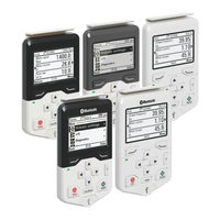
ABB ACH180 User Manual (100 pages)
Assistant control panels
Brand:
ABB
| Category:
Control Panel
| Size: 9.34 MB
Table of Contents
Table of Contents
5
Introduction to the Manual
11
What this Chapter Contains
11
Applicability
12
Compatibility
13
Safety
13
Intended Audience
13
Related Manuals
13
Installation and Start-Up
15
What this Chapter Contains
15
Installation
16
First Start-Up
17
Control Panel Overview
19
What this Chapter Contains
19
Display, Keys and Parts
20
Display
22
Keys
24
Left Softkey
24
Right Softkey
24
Arrow Keys
24
Help
24
Start and Stop
24
Off
25
Hand
25
Auto
25
Loc/Rem
25
Key Shortcuts
25
Control Panel and Panel Platform/Holder Leds
26
USB Connector
26
Wireless Interface
27
RJ45 Connector
27
Type Code Label on the Control Panel
27
Type Code Label on ACS-AP-I, ACS-AP-S, ACH-AP-H and ACS-BP-S Panels
27
Type Code Label on ACS-AP-W and ACH-AP-W Panels
28
Type Code Label on the Control Panel Package
29
Battery Cover
29
Basic Operation
31
What this Chapter Contains
31
User Interface Overview
31
Control Panel Navigation
32
Navigation Memory
32
Home View
33
Navigating in the Home View
33
Help
34
Common User Tasks
34
Basic Operation of the Drive
34
Parameters
35
System Information and Help
35
Faults and Warnings
35
Basic Settings and Assistants
36
Backups
36
Bluetooth Configurations
36
Functions in the Main Menu
37
What this Chapter Contains
37
Menu
38
Navigating in the Menu
39
Parameters
39
Complete List
39
By Function
39
Favorites
40
Editing the List of Favorites
40
Modified
40
Adding Parameters to the Home View
40
Editing Parameters
41
Editing Numeric Parameters
41
Editing Selection List Parameters
42
Editing Bit-Field Parameters
44
Editing Texts
44
Resetting Counters
45
Assistants
45
Launching an Assistant
45
Generating a QR Code
47
Energy Efficiency
48
Event Log
48
History Graphs
48
Trends
49
Load Profile
49
Backups
50
Creating a Parameter Backup
51
Restoring a Parameter Backup
51
System Info
52
Settings
56
Primary Settings
57
I/O
59
Diagnostics
60
Functions in the Options Menu
61
What this Chapter Contains
61
Options Menu
61
Setting the Reference
62
Editing the Contents of the Home View
62
Control of Multiple Drives
67
What this Chapter Contains
67
Connecting Multiple Drives to a Control Panel
67
Selecting Drive Menu
68
Selecting a Drive
68
Control Panel Features with Multiple Drives
69
Control Panel Views
69
The Help Page
69
Graph Data
69
Backups
69
Customized Content
69
Assistants
69
Faults and Warnings with Multiple Drives
70
Faults and Warnings in the Currently Selected Drive
70
Faults and Warnings in Other Drives
70
Fault Tracing
71
What this Chapter Contains
71
Identifying Error and Warning Messages
71
Faults
73
Warnings
73
Maintenance
75
What this Chapter Contains
75
Removing the Control Panel Cover
76
Cleaning the Control Panel
76
Cleaning the Connectors
76
Replacing the Control Panel Battery
77
Control Panel Software Updates
77
Recycling Instructions and Environmental Information
77
External Connections
79
What this Chapter Contains
79
USB Connection
79
Connecting Control Panel to PC USB
80
Connecting Drive Composer PC Tool to a Drive through the Control Panel
81
Connecting in Local Control Mode
81
Connecting in Remote Control Mode
81
Transferring Files between the Control Panel and a PC
82
Bluetooth Connection
82
Connecting Drivetune to a Drive through Bluetooth on the Control Panel
82
Installing Drivetune App on Android Device
82
Installing Drivetune App on Ios Device
82
Pairing the Drive Via Drivetune
83
Connecting Drive Composer Entry to a Drive through Bluetooth on the Control Panel
87
Technical Data
89
What this Chapter Contains
89
Connectors
89
Power Supply (from the Drive)
90
Display
90
Battery
90
Dimensions and Weight
90
Degrees of Protection
91
Materials
91
Environmental Limits
92
IEC Compliance
92
LCD Specifications
92
Bluetooth Interface
93
Bluetooth Encryption
93
Bluetooth Radio Frequency Exposure
94
Bluetooth (BT)
94
Bluetooth Low Energy (BLE)
94
FCC and Industry Canada Certifications
94
Fcc ID: 2Afngapwseries
94
IC: 20555-Apwseries
95
ANATEL Certification
95
CMIIT Certification
95
Markings
95
Disclaimers
97
Generic Disclaimer
97
Cyber Security Disclaimer
97
ABB ACH180 Quick Installation And Start-Up Manual (2 pages)
Brand:
ABB
| Category:
DC Drives
| Size: 2.07 MB
Advertisement
ABB ACH180 Quick Installation And Start-Up Manual (2 pages)
Brand:
ABB
| Category:
Industrial Equipment
| Size: 2.92 MB
Advertisement
Related Products
ABB ACH180-04S
ABB ACH580-PxR-248A-2
ABB ACH580-PxR-156A-4
ABB ACH580-PxR-180A-4
ABB ACH580-PxR-052A-6
ABB ACH580-E-Clipse
ABB ACH580-01-09A5-4
ABB ACH580-01-03A0-4
ABB ACH580-01-044A-4
ABB ACH580-01-088A-4
ABB Categories
Industrial Equipment
Controller
Measuring Instruments
Battery Charger
DC Drives
More ABB Manuals
Login
Sign In
OR
Sign in with Facebook
Sign in with Google
Upload manual
Upload from disk
Upload from URL