Sign In
Upload
Manuals
Brands
ABB Manuals
DC Drives
ACH580-31
ABB ACH580-31 Manuals
Manuals and User Guides for ABB ACH580-31. We have
8
ABB ACH580-31 manuals available for free PDF download: Hardware Manual, Installation Manual, Quick Start Up Manual, Manual, Quick Installation Manual, Quick Installation And Start-Up Manual
ABB ACH580-31 Hardware Manual (284 pages)
INDUSTRIAL DRIVES
Brand:
ABB
| Category:
DC Drives
| Size: 36.01 MB
Table of Contents
Table of Contents
5
Safety Instructions
17
Contents of this Chapter
17
Use of Warnings and Notes
17
General Safety in Installation, Start-Up and Maintenance
18
Electrical Safety in Installation, Start-Up and Maintenance
20
Electrical Safety Precautions
20
Additional Instructions and Notes
21
Printed Circuit Boards
21
Grounding
22
General Safety in Operation
23
Additional Instructions for Permanent Magnet Motor Drives
23
Safety in Installation, Start-Up, Maintenance
23
Safety in Operation
24
Introduction to the Manual
25
Contents of this Chapter
25
Target Audience
25
Purpose of the Manual
25
Categorization by Frame Size and Option Code
25
Quick Installation, Commissioning and Operation Flowchart
26
Terms and Abbreviations
27
Related Documents
29
Operation Principle
31
Contents of this Chapter
31
Active Braking Function (Option +N8056 )
32
DC Voltage Boost Function
32
Benefits of the DC Voltage Boost
33
Impact of DC Voltage Boost on Input Current
33
DC Connection
33
Layout
34
Overview of Power and Control Connections
36
Control Panel
37
Control Panel Door Mounting Kits
38
Control Panel Mounting Platform Cover (Option +J424)
38
Remote Control Panel, Panel Bus
38
Type Designation Label
40
Type Designation Key
41
Basic Code
41
Option Codes
41
Mechanical Installation
43
Contents of this Chapter
43
Cabinet Installation (Option +P940)
43
Flange Mounting (Option +C135)
43
Safety
44
Examining the Installation Site
44
Installation Positions
44
Free Space Requirements
45
Necessary Tools
46
Moving the Drive
47
Unpacking and Examining Delivery
47
Installing the Drive Vertically
53
Installing the Drive Vertically Side by Side
55
Installing the Drive Horizontally
55
Guidelines for Planning the Electrical Installation
57
Contents of this Chapter
57
Limitation of Liability
57
Selecting the Main Supply Disconnecting Device
57
European Union and United Kingdom
58
North America
58
Other Regions
58
Implementing a Fast Switch over between the Power Line and Generator
58
Selecting the Main Contactor
58
North America
59
Other Regions
59
Examining the Compatibility of the Motor and Drive
59
Protecting the Motor Insulation and Bearings
59
Requirements Tables
60
Requirements for ABB Motors, P
60
Kw (134 Hp)
60
Requirements for ABB Motors, P
61
Requirements for Non-ABB Motors, P < 100 Kw (134 Hp)
62
Requirements for Non-ABB Motors, P
63
Abbreviations
64
Availability of D U /D T Filter and Common Mode Filter by Drive Type
64
Additional Requirements for Explosion-Safe (EX) Motors
64
Additional Requirements for ABB Motors of Types Other than M2_, M3_, M4_, HX_ and am
64
Additional Requirements for Braking Applications
64
Additional Requirements for the Regenerative and Low Harmonics Drives
64
Additional Requirements for ABB High-Output and IP23 Motors
64
Additional Requirements for Non-ABB High-Output and IP23 Motors
65
Additional Data for Calculating the Rise Time and the Peak Line-To-Line Voltage
66
Additional Note for Sine Filters
67
Selecting the Power Cables
68
General Guidelines
68
Typical Power Cable Sizes
68
Power Cable Types
68
Preferred Power Cable Types
68
Alternate Power Cable Types
69
Not Allowed Power Cable Types
70
Additional Guidelines - North America
70
Metal Conduit
71
Power Cable Shield
71
Grounding Requirements
72
Additional Grounding Requirements - IEC
73
Additional Grounding Requirements - UL (NEC)
74
Selecting the Control Cables
74
Shielding
74
Signals in Separate Cables
74
Signals that Can be Run in the same Cable
74
Relay Cable
75
Control Panel to Drive Cable
75
PC Tool Cable
75
Routing the Cables
75
General Guidelines - IEC
75
General Guidelines - North America
76
Continuous Motor Cable Shield/Conduit or Enclosure for Equipment on the Motor Cable
77
Separate Control Cable Ducts
78
Protecting the Drive, Input Power Cable, Motor and Motor Cable in Short Circuit Situations and against Thermal Overload
78
Protecting the Drive and the Input Power Cable in Short-Circuits
78
Circuit Breakers
79
Protecting the Motor and Motor Cable in Short-Circuits
79
Protecting the Motor Cables against Thermal Overload
79
Protecting the Motor against Thermal Overload
80
Protecting the Motor against Overload Without Thermal Model or Temperature Sensors
80
Implementing a Motor Temperature Sensor Connection
80
Connecting a Motor Temperature Sensor to the Drive through an Option
81
Module
81
Protecting the Drive against Ground Faults
82
Residual Current Device Compatibility
82
Implementing the Emergency Stop Function
82
Implementing the Safe Torque off Function
82
Implementing the Power Loss Ride-Through Function
82
Using Power Factor Compensation Capacitors with the Drive
83
Using a Safety Switch between the Drive and the Motor
84
Implementing an ATEX-Certified Motor Thermal Protection
84
Controlling a Contactor between Drive and Motor
84
Implementing a Bypass Connection
85
Example Bypass Connection
86
Switching the Motor Power Supply from Drive to Direct-On-Line
86
Switching the Motor Power Supply from Direct-On-Line to Drive
87
Protecting the Contacts of Relay Outputs
87
Limiting Relay Output Maximum Voltages at High Installation Altitudes
88
Implementing a Motor Temperature Sensor Connection
88
Connecting a Motor Temperature Sensor to the Drive through an Option
89
Module
89
Electrical Installation - IEC
91
Contents of this Chapter
91
Safety
91
Required Tools
91
Grounding the Motor Cable Shield at the Motor End
91
Measuring the Insulation
92
Measuring the Insulation Resistance of the Drive
92
Measuring the Insulation Resistance of the Input Power Cable
92
Measuring the Insulation Resistance of the Motor and Motor Cable
92
Measuring the Insulation Resistance of the Brake Resistor Circuit
93
Grounding System Compatibility Check
93
EMC Filter
93
Ground-To-Phase Varistor
94
When to Disconnect EMC Filter or Ground-To-Phase Varistor: TN-S, IT, Corner-Grounded Delta and Midpoint-Grounded Delta Systems and TT Systems
94
Identifying the Grounding System of the Electrical Power Network
97
Disconnecting Integrated EMC Filter and Ground-To-Phase Varistor - Frame R3
98
Disconnecting Integrated EMC Filter and Ground-To-Phase Varistor - Frame R6
99
Disconnecting Integrated EMC Filter and Ground-To-Phase Varistor - Frame R8
100
Connecting the Power Cables
101
Connection Diagram
101
Connection Procedure
102
R8 Power Cable Connection if You Detach the Cable Connectors
109
Connecting the Control Cables
110
Connection Diagram
110
Connection Procedure
110
Installing Option Modules
115
Option Slot 2 (I/O Extension Modules)
115
Option Slot 1 (Fieldbus Adapter Modules)
116
Wiring the Optional Modules
116
Reinstalling Cover(S)
117
Connecting a PC
118
Connecting a Remote Panel, or Chaining One Panel to Several Drives
118
Electrical Installation - North America (NEC)
119
Contents of this Chapter
119
Safety
119
Required Tools
119
Measuring the Installation
120
Grounding System Compatibility Check
120
Connecting the Power Cables
120
Connection Diagram
120
Connection Procedure
121
Connecting the Control Cables
128
Connection Diagram
128
Connection Procedure
128
Installing Optional Modules
132
Reinstalling Cover(S)
133
Connecting a PC
134
Connecting a Remote Panel, or Chaining One Panel to Several Drives
134
Control Unit
135
Contents of this Chapter
135
Layout
136
Default I/O Connection Diagram
137
Switches
139
Additional Information on I/O Connections
139
PNP Configuration for Digital Inputs (X2 & X3)
139
NPN Configuration for Digital Inputs (X2 & X3)
140
Connection for Obtaining 0
140
Connection Examples of Two-Wire and Three-Wire Sensors to Analog Input (AI2)
140
DI5 as Frequency Input
141
DI6 as PTC Input
141
AI1 and AI2 as Pt100, Pt1000, Ni1000, KTY83 and KTY84 Sensor Inputs (X1)
141
Safe Torque off (X4)
142
Technical Data
142
Installation Checklist
147
Contents of this Chapter
147
Checklist
147
Start-Up
151
Contents of this Chapter
151
Reforming the Capacitors
151
Start-Up Procedure
151
Maintenance
153
Contents of this Chapter
153
Maintenance Intervals
153
Description of Symbols
153
Recommended Maintenance Intervals after Start-Up
153
Cleaning the Exterior of the Drive
155
Cleaning the Heatsink
156
Fans
156
Replacing the Main Cooling Fan, Frame R3
157
Replacing the Main Cooling Fan, Frame R6
158
Replacing the Main Cooling Fan, Frame R8
159
Replacing the Auxiliary Cooling Fan of Frame R3, IP55 (UL Type 12) and +C135 IP21 (UL Type 1)
160
Replacing the Auxiliary Cooling Fan, Frame R6
161
Replacing the Second Auxiliary Cooling Fan, IP55 (UL Type 12) Frame R6
162
Replacing the Auxiliary Cooling Fan, Frame R8
163
Replacing the Second Internal Auxiliary Cooling Fan, IP55 (UL Type 12) Frame R8
164
Replacing the Auxiliary Cooling Fan in the IP55 (UL Type 12) Cover, Frame R8
165
Capacitors
167
Reforming the Capacitors
167
Control Panel
167
Drive Leds
167
Functional Safety Components
168
Technical Data
169
Contents of this Chapter
169
Electrical Ratings
169
IEC Ratings
169
UL (NEC) Ratings
170
Definitions
171
Sizing
172
Deratings
172
Derating in Case of Several Situations
172
Surrounding Air Temperature Derating
173
Altitude Derating
174
Switching Frequency Derating
175
Output Voltage Boost Derating
177
Fuses (IEC)
178
Ar Fuses DIN 43653 Stud-Mount
179
Ar Fuses DIN 43620 Blade Style
180
Gg Fuses DIN 43620 Blade Style
180
Calculating the Short-Circuit Current of the Installation
181
Calculation Example
181
Fuses (UL)
182
Circuit Breakers (IEC)
184
ABB Miniature and Molded Case Circuit Breakers
184
Circuit Breakers (UL)
185
Dimensions, Weights and Free Space Requirements
188
Free Space Requirements
188
Package Dimensions and Weights
189
Losses, Cooling Data and Noise
190
Cooling Air Flow and Heat Dissipation for Flange Mounting (Option +C135)
192
Terminal and Entry Data for the Power Cables
194
Iec
194
Ul
194
Terminal and Entry Data for the Control Cables
195
Iec
195
Ul
195
Typical Power Cables
195
Electrical Power Network Specification
198
Motor Connection Data
200
CCU-24 Control Unit Connection Data
201
Efficiency
201
Energy Efficiency Data (EU Ecodesign)
201
Protection Classes for Module
202
Colors
202
Materials
202
Drive
202
Package Materials for Small Wall-Mounted Drives and Converter Modules
202
Package Materials for Large Wall-Mounted Drives and Converter Modules
202
Package Materials for Options, Accessories and Spare Parts
203
Materials of Manuals
203
Disposal
203
Applicable Standards
203
Ambient Conditions
204
Markings
205
Compliance with the en 61800-3:204 + A1:2012
206
Definitions
206
Category C2
207
Category C3
208
Category C4
208
UL Checklist
209
Declarations of Conformity
210
Design Lifetime Expectancy
211
Disclaimers
211
Generic Disclaimer
211
Cybersecurity Disclaimer
211
Dimension Drawings
213
R3, IP21 (UL Type 1)
214
R3 - Option +B056 (IP55, UL Type 12)
215
R6, IP21 (UL Type 1)
216
R6 - Option +B056 (IP55, UL Type 12)
217
R8, IP21 (UL Type 1)
218
R8 - Option +B056 (IP55, UL Type 12)
219
The Safe Torque off Function
221
Contents of this Chapter
221
Description
221
Compliance with the European Machinery Directive and the UK Supply of Machinery (Safety) Regulations
222
Wiring
223
Connection Principle
223
Single ACH580-31 Drive, Internal Power Supply
223
Single ACH580-31 Drive, External Power Supply
224
Wiring Examples
224
Single ACH580-31 Drive, Internal Power Supply
224
Single ACH580-31 Drive, External Power Supply
225
Multiple ACH580-31 Drives, Internal Power Supply
226
Multiple ACH580-31 Drives, External Power Supply
227
Activation Switch
228
Cable Types and Lengths
228
Grounding of Protective Shields
228
Operation Principle
229
Start-Up Including Validation Test
230
Competence
230
Validation Test Reports
230
Validation Test Procedure
230
Use
232
Maintenance
234
Competence
234
Fault Tracing
235
Safety Data
236
Terms and Abbreviations
238
TÜV Certificate
240
Declarations of Conformity
240
Resistor Braking
243
Contents of this Chapter
243
Operation Principle
243
Planning the Braking System
243
Selecting the Default Brake System Components
243
Selecting a Custom Brake Resistor
244
Selecting and Routing the Brake Resistor Cables
245
Minimizing Electromagnetic Interference
245
Maximum Cable Length
245
Placing the Brake Resistors
246
Protecting the System against Thermal Overload
246
Protecting the System in Fault Situations
246
Protecting the Resistor Cable against Short-Circuits
247
Mechanical Installation
247
Electrical Installation
247
Measuring the Installation
247
Connection Diagram
248
Advertisement
ABB ACH580-31 Hardware Manual (254 pages)
Brand:
ABB
| Category:
DC Drives
| Size: 25.65 MB
Table of Contents
Table of Contents
5
Safety Instructions
15
Contents of this Chapter
15
Use of Warnings and Notes in this Manual
15
General Safety in Installation, Start-Up and Maintenance
16
Electrical Safety in Installation, Start-Up and Maintenance
18
Precautions before Electrical Work
18
Additional Instructions and Notes
19
Grounding
20
Additional Instructions for Permanent Magnet Motor Drives
22
Safety in Installation, Start-Up and Maintenance
22
Additional Instruction for DC Connection
22
Introduction to the Manual
23
Contents of this Chapter
23
Applicability
23
Target Audience
23
Purpose of the Manual
23
Categorization by Frame (Size)
23
Quick Installation and Commissioning Flowchart
24
Terms and Abbreviations
24
Related Documents
27
Operation Principle and Hardware Description
29
Contents of this Chapter
29
Operation Principle
30
DC Connection
30
Layout
31
Overview of Power and Control Connections
34
Control Panel
35
Control Panel Mounting Platform Cover (Option +J424)
36
Control Panel Door Mounting Kits
36
Remote Control Panel, Panel Bus
36
Type Designation Label
37
Type Designation Key
38
Mechanical Installation
41
Contents of this Chapter
41
Cabinet Installation (Option +P940)
41
Flange Mounting (Option +C135)
41
Safety
42
Examining the Installation Site
43
Required Tools
45
Moving the Drive
45
Unpacking and Examining Delivery
46
Installing the Drive Vertically
51
Installing the Drive Vertically Side by Side
53
Installing the Drive Horizontally
53
Guidelines for Planning the Electrical Installation
55
Contents of this Chapter
55
Selecting the Supply Disconnecting Device
55
European Union
55
Other Regions
56
Examining the Compatibility of the Motor and Drive
56
Protecting the Motor Insulation and Bearings
56
Requirements Table
57
Additional Requirements for ABB Motors of Types Other than M2_, M3_, M4_, HX_ and
59
Additional Requirements for the Regenerative and Low Harmonic Drives
59
Additional Requirements for ABB High-Output and IP23 Motors
59
Additional Requirements for Non-ABB High-Output and IP23 Motors
60
Additional Data for Calculating the Rise Time and Peak Line-To-Line Voltage
60
Additional Note for Sine Filters
62
Selecting the Power Cables
62
General Guidelines, IEC and North America
62
Additional Guidelines, IEC and North America
63
Preferred Power Cable Types
63
Power Cable Types for Limited Use
64
Not Allowed Power Cable Types
65
Additional Guidelines, North America
65
Conductor Type, IEC and North America
67
Power Cable Shield, IEC and North America
67
Typical Power Cable Sizes
68
IEC Ratings
69
UL (NEC) Ratings
70
Selecting the Control Cables
70
Shielding
70
Signals in Separate Cables
71
Signals Allowed to be Run in the same Cable
71
Relay Cable
71
Control Panel Cable
71
Drive Composer PC Tool Cable
71
Routing the Cables
71
General Guidelines, IEC
71
General Guidelines, North America
72
Separate Control Cable Ducts
74
Continuous Motor Cable Shield or Enclosure for Equipment on the Motor Cable
74
Implementing Thermal Overload and Short-Circuit Protection
75
Protecting the Drive and Input Power Cable in Short-Circuits
75
Circuit Breakers
75
Protecting the Motor and Motor Cable in Short-Circuits
75
Protecting the Drive and the Input Power and Motor Cables against Thermal Overload
75
Protecting the Motor against Thermal Overload
75
Implementing a Ground Fault Detection Function
76
Residual Current Device Compatibility
76
Implementing the Emergency Stop Function
76
Implementing the Safe Torque off Function
76
Implementing the ATEX-Certified Safe Motor Disconnection Function (Option +Q971)
76
Implementing the Undervoltage Control (Power-Loss Ride-Through)
76
Using a Safety Switch between the Drive and the Motor
77
Using a Contactor between the Drive and the Motor
77
Protecting the Contacts of Relay Outputs
77
Limiting Relay Output Maximum Voltages at High Installation Altitudes
78
Implementing a Motor Temperature Sensor Connection
79
Connection of Motor Temperature Sensor to the Drive Via an Option Module
80
Connection of Motor Temperature Sensor to the Drive Via a Relay
81
Ptc (Iec 60800-5-1)
81
Pt100 (IEC 60800-5-1)
81
Electrical Installation - IEC
83
Contents of this Chapter
83
Warnings
83
Grounding the Motor Cable Shield at the Motor End
84
Measuring the Insulation
84
Drive
84
Input Power Cable
84
Motor and Motor Cable
84
Brake Resistor Assembly
85
Tems
86
EMC Filter
86
Ground-To-Phase Varistor
86
When to Disconnect EMC Filter or Ground-To-Phase Varistor: TN-S, IT, Corner-Grounded Delta and Midpoint-Grounded Delta Systems and TT Systems
87
Identifying Different Types of Electrical Power Systems
89
Disconnecting Internal EMC Filter and Ground-To-Phase Varistor - Frame R3
90
Disconnecting Internal EMC Filter and Ground-To-Phase Varistor - Frame R6
91
Disconnecting Internal EMC Filter and Ground-To-Phase Varistor -Frame R8
92
Connecting the Power Cables
93
Connection Diagram
93
Connection Procedure
94
R8 Power Cable Connection if You Detach the Cable Connectors
101
Connecting the Control Cables
103
Default I/O Connection Diagram (HVAC Default Configuration)
104
Switches
105
Additional Information on I/O Connections
105
PNP Configuration for Digital Inputs
106
NPN Configuration for Digital Inputs
106
Connection for Obtaining 0
107
Connection Examples of Two-Wire and Three-Wire Sensors
108
DI5 as Frequency Input
108
DI6 as PTC Input
108
AI1 and AI2 as Pt100, Pt1000, Ni1000, KTY83 and KTY84 Sensor Inputs (X1)
109
Safe Torque off (X4)
109
Control Cable Connection Procedure
110
Installing Optional Modules
114
Mechanical Installation of Option Modules
114
Option Slot 2 (I/O Extension Modules)
114
Option Slot 1 (Fieldbus Adapter Modules)
115
Wiring the Optional Modules
115
Reinstalling Cover(S)
116
Connecting a PC
117
Connecting a Remote Panel, or Chaining One Panel to Several Drives
117
Electrical Installation - North America
119
Contents of this Chapter
119
Warnings
119
Required Tools
119
Measuring the Insulation
119
Drive
120
Input Power Cable
120
Motor and Motor Cable
120
Brake Resistor Assembly
120
Tems
121
Connecting the Power Cables
122
Connection Diagram
122
Connection Procedure
123
R8 Power Cable Connection if You Detach the Connectors
130
Connecting the Control Cables
132
Default I/O Connection Diagram (HVAC Default Configuration)
133
Switches
134
Additional Information on Control Connections
134
Control Cable Connection Procedure
135
Installing Optional Modules
139
Reinstalling Cover(S)
139
Connecting a PC
139
Connecting a Remote Panel, or Chaining One Panel to Several Drives
140
Installation Checklist
141
Contents of this Chapter
141
Warnings
141
Checklist
141
Start-Up
143
Contents of this Chapter
143
Start-Up Procedure
143
Maintenance and Hardware Diagnostics
145
Contents of this Chapter
145
Maintenance Intervals
145
Description of Symbols
146
Recommended Annual Maintenance Actions by the User
146
Recommended Maintenance Actions by the User
146
Heatsink
147
Fans
147
Replacing the Main Cooling Fan, Frame R3
148
Replacing the Main Cooling Fan, Frame R6
149
Replacing the Main Cooling Fan, Frame R8
150
Replacing the Main Cooling Fan, Frame R6
150
Replacing the Auxiliary Cooling Fan, IP55 (UL Type 12) Frame R3
151
Replacing the Auxiliary Cooling Fan, Frame R6
152
Stop the Drive and Disconnect It from the Power Line. Wait for 5 Minutes and then Make Sure by Measuring that There Is no Voltage. See Section Electrical Work on Page
152
Replacing the Auxiliary Cooling Fan, Frame R8
153
Replacing the Second Auxiliary Cooling Fan IP55 (UL Type 12), Frame R8
154
Capacitors
156
Reforming the Capacitors
156
Control Panel
156
Drive Leds
157
Technical Data
159
Contents of this Chapter
159
Ratings
159
IEC Ratings
159
UL (NEC) Ratings
160
Definitions
161
Sizing
161
Derating
161
Derating in Case of Several Situations
161
Example
161
Ambient Temperature Derating, IP21 (UL Type 1)
162
Ambient Temperature Derating, IP55 (UL Type 12)
163
Ambient Temperature Derating in Table Format
164
Altitude Derating
165
Switching Frequency Derating
167
Fuses (IEC)
169
Ar Fuses DIN 43653 Stud-Mount
169
Ar Fuses DIN 43620 Blade Style
169
Gg Fuses DIN 43620 Blade Style
170
Calculating the Short-Circuit Current of the Installation
171
Fuses (UL)
173
Circuit Breakers
174
Dimensions, Weights and Free Space Requirements
174
Free Space Requirements
174
Losses, Cooling Data and Noise
175
Cooling Air Flow and Heat Dissipation for Flange Mounting (Option +C135)
176
Terminal and Entry Data for the Power Cables
177
Iec
177
UL Listed Cable Lugs and Tools
179
Terminal and Entry Data for the Control Cables
180
Iec
180
Electrical Power Network Specification
180
Voltage (U1)
180
Motor Connection Data
182
CCU-24 Control Unit Connection Data
184
Efficiency
188
Degree of Protection
188
Materials
188
Applicable Standards
190
Ambient Conditions
191
Markings
192
EMC Compliance (IEC/EN 61800-3:2004 + A1:2012)
193
Definitions
193
Category C2
194
Category C3
194
Category C4
195
UL Checklist
195
EU Declaration of Conformity (Machinery Directive)
197
Disclaimers
197
General Disclaimer
197
Cybersecurity Disclaimer
197
Dimension Drawings
199
Contents of this Chapter
199
R3, IP21 (UL Type 1)
200
R3 - Option +B056 (IP55, UL Type 12)
201
R6, IP21 (UL Type 1)
202
R6 - Option +B056 (IP55, UL Type 12)
203
R8, IP21 (UL Type 1)
204
R8 - Option +B056 (IP55, UL Type 12)
205
The Safe Torque off Function
207
Contents of this Chapter
207
Description
207
Compliance with the European Machinery Directive
208
Wiring
208
Connection with Internal +24 V DC Power Supply
209
Connection with External +24 V DC Power Supply
210
Wiring Examples
210
Activation Switch
211
Cable Types and Lengths
211
Grounding of Protective Shields
212
Operation Principle
212
Start-Up Including Acceptance Test
212
Competence
212
Acceptance Test Reports
212
Acceptance Test Procedure
212
Use
214
Maintenance
215
Competence
216
Fault Tracing
216
Safety Data (SIL, PL)
217
Abbreviations
218
Resistor Braking
219
Contents of this Chapter
219
Operation Principle and Hardware Description
219
Planning the Braking System
219
Selecting the Brake Circuit Components
219
Selecting a Custom Resistor
220
Selecting and Routing the Brake Resistor Cables
220
Minimizing Electromagnetic Interference
221
Maximum Cable Length
221
EMC Compliance of the Complete Installation
221
Placing the Brake Resistors
221
Protecting the System against Thermal Overload
222
Protecting the System in Fault Situations
222
Protecting the Resistor Cable against Short-Circuits
222
Mechanical Installation
223
Electrical Installation
223
Measuring the Insulation
223
Connection Diagram
223
Connection Procedure
223
Start-Up
223
Technical Data
223
Ratings
223
Terminals and Cable Lead-Through Data
223
Common Mode, Du/Dt and Sine Filters
225
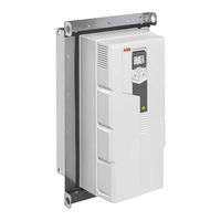
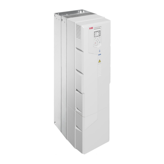
ABB ACH580-31 Installation Manual (238 pages)
Flange mounting kit
Brand:
ABB
| Category:
Industrial Equipment
| Size: 45.6 MB
Table of Contents
Table of Contents
5
Introduction to the Supplement
11
Contents of this Chapter
11
Applicability
11
Safety Instructions
11
Target Audience
11
Purpose of the Supplement
12
Contents of the Manual
12
Related Documents
12
Hardware Description
13
Contents of this Chapter
13
Product Overview
13
Layout and Mounting Position
13
Example: Tilted Position
14
Example: Upright Position
15
Degree of Protection
15
ACS880-01, ACS580-01, ACSH580-01 and ACQ580-01
15
ACS880-11, ACS880-31, ACH580-31 and ACX580-31
15
Special Requirements
16
Ordering Codes
17
Mechanical Installation for ACS880-01
19
Contents of this Chapter
19
Safety
19
Examining the Installation Site
20
Additional Requirements for Cabinet Installations
20
Necessary Tools
20
Moving the Drive
20
Unpacking and Examining the Delivery
21
Transport Package Contents
21
Frames R1 to R5
22
Frames R6 to R9
23
Flange Mounting Kit Package Contents
24
Frames R1 to R3
24
Frames R4 to R5
25
Frames R6 to R9
26
Mounting Template
27
Installing the Drive
28
Free Space Requirements
28
Installing Drives above One Another
29
Installation Procedure
30
Frames R1 to R3
30
Frames R4 to R5
39
Frames R6 to R9
47
Mechanical Installation for ACS580-01, ACH580-01 and ACQ580-01
53
Contents of this Chapter
53
Safety
53
Examining the Installation Site
54
Additional Requirements for Cabinet Installations
54
Necessary Tools
54
Moving the Drive
54
Unpacking and Examining the Delivery
55
Transport Package Contents
55
Frames R0 to R4
55
Frames R5
55
Frames R6 to R9
56
Flange Mounting Kit Package Contents
57
Frames R0 to R4
57
Frame R5
58
Frames R6 to R9
59
Mounting Template
59
Installing the Drive
60
Free Space Requirements
60
Installing Drives above One Another
61
Installation Procedure
62
Frames R0 to R5
62
Frames R6 to R9
72
Mechanical Installation for ACS880-11 and ACS880-31
77
Contents of this Chapter
77
Safety
77
Examining the Installation Site
78
Additional Requirements for Cabinet Installations
78
Necessary Tools
78
Moving the Drive
78
Unpacking and Examining the Delivery
79
Transport Package Contents
79
Frame R3
80
Frames R6 and R8
81
Flange Mounting Kit Package Contents
82
Frame R3
82
Frames R6 and R8
83
Mounting Template
83
Installing the Drive
84
Free Space Requirements
84
Installing Drives above One Another
85
Installation Procedure
86
Frame R3
86
Frames R6 and R8
92
Mechanical Installation for ACH580-31 and ACQ580-31
101
Contents of this Chapter
101
Safety
102
Examining the Installation Site
102
Additional Requirements for Cabinet Installations
102
Necessary Tools
103
Moving the Drive
103
Unpacking and Examining the Delivery
103
Transport Package Contents
103
Frame R3
104
Frames R6 and R8
105
Flange Mounting Kit Package Contents
106
Frame R3
106
Frames R6 and R8
107
Example Mounting Template
108
Installing the Drive
109
Free Space Requirements
109
Installing Drives above One Another
110
Installation Procedure
111
Frame R3
111
Frames R6 and R8
118
Dimension Drawings for ACS880-01
125
Contents of this Chapter
125
Frame R1
126
Attaching Points and Hole Dimensions
127
Frame R2
128
Attaching Points and Hole Dimensions
129
Frame R3
130
Attaching Points and Hole Dimensions
131
Frame R4
132
Attaching Points and Hole Dimensions
134
Frame R5
135
Attaching Points and Hole Dimensions
137
Frame R6
138
Attaching Points and Hole Dimensions
140
Frame R7
141
Attaching Points and Hole Dimensions
143
Frame R8
144
Attaching Points and Hole Dimensions
146
Frame R9
147
Attaching Points and Hole Dimensions
149
Dimension Drawings for ACS580-01, ACH580-01 and ACQ580-01
151
Contents of this Chapter
151
Frame R0
152
Frame R1
154
Attaching Points and Hole Dimensions
156
Frame R2
157
Attaching Points and Hole Dimensions
159
Frame R3
160
Attaching Points and Hole Dimensions
162
Frame R1
163
Attaching Points and Hole Dimensions
165
Frame R2
166
Attaching Points and Hole Dimensions
168
Frame R3
169
Attaching Points and Hole Dimensions
171
Frame R4
172
Frame R5
174
Frames R4
176
Attaching Points and Hole Dimensions
176
Frame R6
177
Attaching Points and Hole Dimensions
179
Frame R7
180
Attaching Points and Hole Dimensions
182
Advertisement
ABB ACH580-31 Quick Start Up Manual (104 pages)
HVAC control program
Brand:
ABB
| Category:
DC Drives
| Size: 3.58 MB
Table of Contents
Diagnostics Menu
12
DE - Kurzanleitung für die Inbetriebnahme
13
ES - Guía Rápida de Puesta en Marcha
23
FI - Pika-Aloitusopas
33
FR - Guide de Mise en Route
43
Menu Diagnostic
52
IT - Guida Rapida All'avviamento
53
NL - Beknopte Opstartgids
63
PT - Guia de Início Rápido
73
RU - Краткое Руководство По Вводу В Эксплуатацию
83
Техника Безопасности
83
SV - Snabbguide För Idrifttagning
93
Further Information
103
ABB ACH580-31 Manual (52 pages)
drives with flangemounting kit
Brand:
ABB
| Category:
DC Drives
| Size: 8.83 MB
Table of Contents
Table of Contents
5
Introduction to the Supplement
7
Contents of this Chapter
7
Applicability
7
Target Audience
7
Purpose of the Supplement
7
Related Documents
8
Hardware Description
11
Contents of this Chapter
11
Product Overview
11
Layout and Mounting Position
11
Example: Tilted Position, Frame R3
12
Example: Upright Position, Frames R6 and R8
13
Degree of Protection
13
Special Requirements
16
Ordering Codes
16
Mechanical Installation
17
Contents of this Chapter
17
Safety Instructions
17
Examining the Installation Site
18
Additional Requirements for Cabinet Installations
18
Required Tools
19
Moving the Drive
19
Unpacking and Examining the Delivery
19
Transport Package Contents
19
Frame R3
20
Frames R6 and R8
21
Flange Mounting Kit Package Contents
21
Frame R3
22
Frames R6 and R8
23
Mounting Template
24
Installing the Drive
25
Free Space Requirements
25
Installing Drives above One Another
26
Installation Procedure
27
Frame R3
27
Installing the Gasket (IP21 [UL Type 1])
27
Installing the Auxiliary Fan (IP21 [UL Type 1])
27
Installing the Flange
29
Frames R6 and R8
34
Installation Procedure
34
Dimension Drawings
41
Contents of this Chapter
41
Frame R3, IP21 (UL Type 1)
42
Attaching Points and Opening Dimensions, Frame R3
43
Frame R6, IP 21 (UL Type 1)
44
Hood
45
Attaching Points and Opening Dimensions, Frame R6
46
Frame R8, IP21 (UL Type 1)
47
Hood
48
Attaching Points and Opening Dimensions, Frame R8
49
Further Information
51
ABB ACH580-31 Quick Installation Manual (33 pages)
Brand:
ABB
| Category:
DC Drives
| Size: 20.29 MB
Table of Contents
List of Related Manuals in English
2
Obey the Safety Instructions
3
Check if Capacitors Need to be Reformed
4
Select the Power Cables
4
Ensure Cooling
4
E - Attach the Warning Stickers in Local Languages
5
F - Connect the Power Cables
6
G - Connect the Control Cables
7
H - Reinstall Cover(S)
8
C - Check the Compatibility with IT (Ungrounded) and Corner-Grounded Delta Systems
13
D - Check the Insulation of the Power Cables and the Motor
14
Further Information
31
Product and Service Inquiries
31
Product Training
31
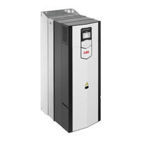
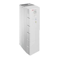
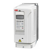
ABB ACH580-31 Manual (16 pages)
Converter modules with electrolytic DC capacitors in the DC link
Brand:
ABB
| Category:
Control Unit
| Size: 0.42 MB
Table of Contents
Table of Contents
3
1 Introduction
5
Contents of this Chapter
5
Applicability
5
ABB Low Voltage AC Drives
5
ABB Wind Turbine Converters
6
ABB Solar Inverters
6
Target Audience
6
Purpose of the Manual
6
Safety Instructions
6
2 Reforming the Capacitors
9
Contents of this Chapter
9
Overview of the Reforming
9
Reforming Time
9
Checking the Converter Age
10
Reforming with Power on for 30 Minutes
11
Reforming with External DC Power Supply
11
Reforming with External Diode Bridge
13
Further Information
15
ABB ACH580-31 Quick Installation And Start-Up Manual (16 pages)
Brand:
ABB
| Category:
DC Drives
| Size: 10.03 MB
Table of Contents
Install the Drive on the Wall
2
Remove the Covers
3
Connect the Power Cables
4
Connect the Control Cables
7
Start-Up the Drive
10
Motor Overload Protection
11
Fieldbus Communication
11
Warnings and Faults
11
Terminal Data
13
Dimensions, Weights and Free Space Requirements
13
Ambient Conditions
13
Safe Torque off (Sto)
14
Technical Data
14
Related Documents
15
Declarations of Conformity
15
Advertisement
Related Products
ABB ACH580-31-09A5-4
ABB ACH580-31-12A7-4
ABB ACH580-31-018A-4
ABB ACH580-31-026A-4
ABB ACH580-31-033A-4
ABB ACH580-31-039A-4
ABB ACH580-31-046A-4
ABB ACH580-31-062A-4
ABB ACH580-31-073A-4
ABB ACH580-31-088A-4
ABB Categories
Industrial Equipment
Controller
Measuring Instruments
Battery Charger
DC Drives
More ABB Manuals
Login
Sign In
OR
Sign in with Facebook
Sign in with Google
Upload manual
Upload from disk
Upload from URL