Sign In
Upload
Manuals
Brands
ABB Manuals
Controller
ACQ580-07
ABB ACQ580-07 Water Drive Manuals
Manuals and User Guides for ABB ACQ580-07 Water Drive. We have
4
ABB ACQ580-07 Water Drive manuals available for free PDF download: Hardware Manual, User Manual, Electrical Planning Instructions
ABB ACQ580-07 Hardware Manual (324 pages)
DRIVES FOR WATER
Brand:
ABB
| Category:
DC Drives
| Size: 40.81 MB
Table of Contents
Table of Contents
10
Table of Contents
13
Cabinet Layout - R10 and R11 (Top Entry and Exit of Cables, Options +H351 and +H353)
51
Mounting Plate - R10 and R11
52
Cooling Air Flow
54
Door Switches and Lights
55
Main Switch-Disconnector Q1
55
Control Panel
55
Control by PC Tools
56
Common Mode Filter
56
Overview of Power and Control Connections
57
Descriptions of Options
58
Degree of Protection
58
Definitions
58
IP21 (UL Type 1)
58
IP42 (UL Type 1 Filtered) (Option +B054)
58
IP54 (UL Type 12) (Option +B055)
58
UL Listed (Option +C129)
58
Plinth Height (Options +C164 and +C179)
59
Empty Cubicles on Right (Options +C196
59
Empty Cubicles on Left (Options +C199
59
Du/Dt Filter (Option +E205)
59
Common Mode Filter (Option +E208)
59
Molded Case Circuit Breaker (MCCB, Option +F289)
59
Cabinet Heater with External Supply (Option +G300)
60
Terminals for External Control Voltage (Option +G307)
60
Ready/Run/Fault Lights (Options +G327
60
Top Cable Entry/Exit (Options +H351 and +H353)
60
Cable Conduit Entry (Option +H358)
60
Additional Terminal Block X504 (Option +L504)
61
Starter for Auxiliary Motor Fan (Options +M6Xx)
61
What the Option Contains
61
Description
61
Cables Accepted by the Terminals of the Additional I/O Terminal Block (Option +L504)
61
Type Designation Label
62
Type Designation Key
62
Basic Code
62
Option Codes
63
Mechanical Installation
67
Contents of this Chapter
67
Examining the Installation Site
67
Necessary Tools
68
Moving and Unpacking the Drive
68
Unpacking the Transport Package
71
Examining the Delivery
72
Lifting the Cabinet
72
Lifting Lugs
74
Moving the Cabinet after Unpacking
76
Moving the Cabinet with Rollers
77
Moving the Cabinet to Its Final Placement with a Slate Bar
77
Attaching the Cabinet to the Floor and Wall or Roof
77
General Rules
77
Attaching the Cabinet (Non-Marine Units)
78
Alternative 1 - Clamping
78
Alternative 2 - Using the Holes Inside the Cabinet
80
Alternative 3 - Cabinets with Plinth Options +C164 and +C179
81
Miscellaneous
82
Cable Duct in the Floor below the Cabinet
82
Arc Welding
82
Guidelines for Planning the Electrical Installation
83
Contents of this Chapter
83
Limitation of Liability
83
Selecting the Supply Disconnecting Device
83
Selecting the Main Contactor or Breaker
83
Examining the Compatibility of the Motor and Drive
84
Protecting the Motor Insulation and Bearings
84
Requirements Table
84
Availability of Du/Dt Filter and Common Mode Filter by Drive Type
87
Additional Requirements for Explosion-Safe (EX) Motors
87
Additional Requirements for ABB Motors of Types Other than M2_, M3_, M4_, HX_ and am
87
Additional Requirements for ABB High-Output and IP23 Motors
87
Additional Requirements for Non-ABB High-Output and IP23 Motors
88
Additional Data for Calculating the Rise Time and the Peak Line-To-Line Voltage
89
Selecting the Power Cables
91
General Guidelines
91
Typical Power Cable Sizes
92
Power Cable Types
92
Preferred Power Cable Types
92
Alternate Power Cable Types
93
Not Allowed Power Cable Types
94
Additional Guidelines, North America
94
Metal Conduit
95
Power Cable Shield
95
Selecting the Control Cables
96
Shielding
96
Signals in Separate Cables
96
Signals that Can be Run in the same Cable
96
Relay Cable
96
Control Panel to Drive Cable
96
PC Tool Cable
96
Routing the Cables
97
General Guidelines - IEC
97
General Guidelines - North America
98
Continuous Motor Cable Shield/Conduit or Enclosure for Equipment on the Motor Cable
99
Separate Control Cable Ducts
99
Implementing Short-Circuit and Thermal Overload Protection
99
Protecting the Input Cabling and Drive in Short-Circuits
99
Protecting the Motor and Motor Cable in Short-Circuits
100
Protecting the Drive and the Power Cables against Thermal Overload
100
Protecting the Motor against Thermal Overload
100
Protecting the Drive against Ground Faults
101
Residual Current Device Compatibility
101
Implementing the Emergency Stop Function
101
Implementing the Safe Torque off Function
101
Implementing the Power Loss Ride-Through Function
101
Using Power Factor Compensation Capacitors with the Drive
102
Using a Safety Switch between the Drive and the Motor
103
Implementing an ATEX-Certified Motor Thermal Protection
103
Controlling a Contactor between Drive and Motor
103
Implementing a Bypass Connection
104
Protecting the Contacts of Relay Outputs
104
Implementing a Motor Temperature Sensor Connection
105
Connecting Motor Temperature Sensor to the Drive Via an Option Module
106
Supplying Power for the Auxiliary Circuits
107
Electrical Installation
109
Contents of this Chapter
109
Warning
109
Attaching the Device Stickers on the Cabinet Door
109
Layout of the Cable Entries (Frames R6
110
Layout of the Cable Entries (Frames R10 and R11)
111
Connecting the Motor Cable at the Motor End
111
Measuring the Insulation
112
Measuring the Insulation of the Drive
112
Measuring the Insulation of the Input Power Cable
112
Measuring the Insulation of the Motor and Motor Cable
112
Grounding System Compatibility Check
113
Connecting the Power Cables
113
Preparing the Cable Ends and Making 360-Degree Grounding at the Cable Entry
113
Connection Diagram
115
Connection Procedure (Frames R6
117
Connection Procedure (Frames R6 and R7 with Options +H351 and +H353)
118
H353)
120
Connection Procedure
120
Tighten the Power Cable Screws to the Torque Given in Terminal and Entry Data for the Power Cables
122
Reinstall the Shrouds and Mounting Plate
122
Connection Procedure (Frames R10 and R11)
123
H353)
124
Do the Steps in Section Electrical Safety Precautions (Page 20) before You Start the Work
124
Open the Cabinet Door
124
Remove the Door Fan Mounting Plate. See Section
125
R10 and R11)
125
Connect the Twisted Shields of the Motor Cables to the Ground Bar and the Phase Conductors to the U2, V2 and W2 Terminals of the Drive Module
126
Connect the Twisted Shields of the Input Cables and Separate Ground Cable (if Present)
126
To the PE Terminal of the Cabinet and the Phase Conductors to the L1, L2 and L3
126
Connecting the Control Cables
127
Overview of Control Cable Connection Procedure
128
Grounding the Outer Shields of the Control Cables at the Cabinet Entry
128
Routing the Control Cables Inside the Cabinet
132
Connecting External Wiring to the Control Unit or Optional I/O Terminal Block
135
Connecting the Emergency Stop Push Buttons (Options +Q951 and +Q963)
136
Frames R6
136
Frames R10 and R11
137
Connecting the Safe Torque off Circuit
137
G300)
137
Setting the Voltage Range of the Auxiliary Control Voltage Transformer (T21)
138
Connecting a PC
139
Installing Option Modules
140
Option Slot 2 (I/O Extension Modules)
140
Option Slot 1 (Fieldbus Adapter Modules)
141
Wiring the Optional Modules
141
Control Unit
143
Contents of this Chapter
143
Layout
144
Default I/O Connection Diagram
145
DI6 for Internal Overtemperature Supervision with Option +E205 in Frames R10 and R11
146
PNP and NPN Configurations for Digital Inputs
147
PNP Configurations with Option +L504
147
NPN Configurations with Option +L504
147
PNP Configurations Without Option +L504
148
NPN Configurations Without Option +L504
148
Switches
149
Additional Information on I/O Connections
149
Connection for Obtaining 0
149
Connection Examples of Two-Wire and Three-Wire Sensors to Analog Input (AI2)
150
DI5 as Frequency Input
150
DI6 as PTC Input
150
AI1 and AI2 as Pt100, Pt1000, Ni1000, KTY83 and KTY84 Sensor Inputs (X1)
151
Safe Torque off (X4)
151
Technical Data
152
Installation Checklist
157
Contents of this Chapter
157
Checklist
157
Start-Up
159
Contents of this Chapter
159
Start-Up Procedure
159
Fault Tracing
161
Contents of this Chapter
161
Warning and Fault Messages
161
Maintenance
163
Contents of this Chapter
163
Maintenance Intervals
163
Descriptions of Symbols
163
Recommended Annual Maintenance Actions by the User
164
Recommended Maintenance Intervals after Start-Up
164
Cleaning the Interior of the Cabinet
165
Cleaning the Air Inlet (Door) Meshes (IP42 / UL Type 1 Filtered)
165
Replacing the Air Filters (IP54 / UL Type 12)
166
Inlet (Door) Filters (IP54 / UL Type 12)
167
Outlet (Roof) Filters (IP54 / UL Type 12)
167
Heatsink (Frames R6 to R9)
168
Fans
168
Replacing the Door Fan (Frames R6
168
Replacing the Cabinet Fan (Frames R6
169
Replacing the Door Fan (Frames R10 and R11)
170
Replacing the Cabinet Fan (Frames R10 and R11, IP54 / UL Type 12)
172
Replacing the Drive Module Main Fans (Frames R6
173
Replacing the Drive Module Main Fans (Frame R9)
174
Replacing the Drive Module Main Fans (Frames R10 and R11)
175
Replacing the Auxiliary Cooling Fan of the Drive Module (Frames R6
176
Replacing the Circuit Board Compartment Cooling Fans (Frames R10 and R11)
178
Replacing the Drive Module (Frames R6
178
Replacing the Drive Module (Frames R10 and R11)
186
Replacing the Drive Module (Frames R10 and R11, IP54 / UL Type 12)
192
Capacitors
198
Reforming the Capacitors
198
Fuses
198
Replacing AC Fuses (Frames R6 and R7)
198
Replacing AC Fuses
199
Control Panel
200
Cleaning the Control Panel
200
Replacing the Battery
200
Technical Data
201
Contents of this Chapter
201
Ratings
201
IEC Ratings
201
UL (NEC) Ratings
202
Definitions
203
Output Derating
203
Ambient Temperature Derating
203
Drive Types Other than -0414A-4 and -0430A-4
203
Drive Types -0414A-4 and -0430A-4
204
Altitude Derating
204
Deratings for Special Settings in the Drive Control Program
205
Fuses (IEC)
206
Fuses (UL)
208
Fuses for Branch Circuit Protection
209
Dimensions and Weights
209
Free Space Requirements
210
Maximum Allowed Plinth Height for the Extraction/Installation Ramp
211
Typical Power Cable Sizes
211
Losses, Cooling Data and Noise
212
Terminal and Entry Data for the Power Cables
213
IEC - Standard Configuration
213
IEC - with Option +E205
214
Standard Configuration
214
With Option +E205
215
Connection Drawings
216
Terminal and Connection Data for Auxiliary Control Circuits
242
Electrical Power Network Specification
243
Motor Connection Data
243
Control Unit Connection Data
244
Efficiency
244
Protection Classes
244
Ambient Conditions
245
Auxiliary Circuit Power Consumption
246
Materials
246
Cabinet
246
Finish
246
Package
246
Vertical Package
246
Horizontal Package
247
Package Dimensions and Weights for Drives Without Empty Cubicles (Without Options +C196
247
Package Weights
248
Applicable Standards
249
Markings
250
CE Marking
250
Compliance with the European Low Voltage Directive
250
Compliance with the European EMC Directive
251
Compliance with the European Machinery Directive
251
Compliance with the en 61800-3:2004
252
Definitions
252
Category C2
252
Category C3
252
Category C4
253
UL Marking
254
UL and CSA Checklist
254
Design Lifetime Expectancy
255
Disclaimers
256
Generic Disclaimer
256
Cybersecurity Disclaimer
256
Dimension Drawings
257
Frames R6 and R7 (IP21, UL Type 1)
258
Frames R6 and R7 (+B054: IP42, UL Type 1 Filtered)
259
Frames R6 and R7 (+B055: IP54, UL Type 12)
260
Frames R6 and R7 (+H351 and +H353: Top Entry and Exit)
261
Frames R6 and R7 (+F289)
262
Frames R6 and R7 (+F289, +H351, +H353)
263
Frames R8 and R9 (IP21, UL Type 1)
264
Frames R8 and R9 (+B054: IP42, UL Type 1 Filtered)
265
Frames R8 and R9 (+B055: IP54, UL Type 12)
266
Frames R8 and R9 (+H351 and +H353: Top Entry and Exit)
267
Frames R8 and R9 (+F289)
268
Frames R8 and R9 (+F289, +H351, +H353)
269
Frames R10 and R11 (IP21, UL Type 1)
270
Frames R10 and R11 (+B054: IP42, UL Type 1 Filtered)
271
Frames R10 and R11 (+B055: IP54, UL Type 12)
272
Frames R10 and R11 (+F289)
273
Frames R10 and R11 (+H351, +H353)
274
Frames R10 and R11 (+B054: IP42, UL Type 1 Filtered, +H351, +H353)
275
Frames R10 and R11 (+B055: IP54, UL Type 12, +H351, +H353)
276
The Safe Torque off Function
277
Contents of this Chapter
277
Description
277
Compliance with the European Machinery Directive
278
Wiring
279
Connection Principle
279
Single ACQ580-07 Drive, Internal Power Supply
279
Single ACQ580-07 Drive, External Power Supply
280
Wiring Examples
280
Single ACQ580-07 Drive, Internal Power Supply
280
Single ACQ580-07 Drive, External Power Supply
281
Multiple ACQ580-07 Drives, Internal Power Supply
282
Multiple ACQ580-07 Drives, External Power Supply
283
Activation Switch
284
Cable Types and Lengths
284
Grounding of Protective Shields
284
Operation Principle
285
Start-Up Including Acceptance Test
286
Competence
286
Acceptance Test Reports
286
Acceptance Test Procedure
286
Use
288
Maintenance
290
Competence
290
Fault Tracing
291
Safety Data
292
Abbreviations
293
TÜV Certificate
294
Declaration of Conformity
295
CHDI-01 115/230 V Digital Input Extension Module
297
Contents of this Chapter
297
Product Overview
297
Layout and Connection Examples
298
Mechanical Installation
299
Necessary Tools
299
Unpacking and Examining the Delivery
299
Installing the Module
299
Electrical Installation
299
Wiring
299
Start-Up
299
Setting the Parameters
299
Parameter Setting Example for Relay Output
300
Fault and Warning Messages
300
Technical Data
300
Dimension Drawing
301
CMOD-01 Multifunction Extension Module
303
Contents of this Chapter
303
Product Overview
303
Layout and Example Connections
304
Mechanical Installation
305
Necessary Tools
305
Unpacking and Examining the Delivery
305
Installing the Module
305
Electrical Installation
305
Wiring
305
Start-Up
306
Setting the Parameters
306
Diagnostics
307
Faults and Warning Messages
307
Leds
307
Technical Data
307
Dimension Drawing
308
CMOD-02 Multifunction Extension Module
311
Contents of this Chapter
311
Product Overview
311
Layout and Example Connections
312
Mechanical Installation
313
Necessary Tools
313
Unpacking and Examining the Delivery
313
Installing the Module
313
Electrical Installation
313
Necessary Tools and Instructions
313
Wiring
314
Start-Up
314
Setting the Parameters
314
Diagnostics
314
Faults and Warning Messages
314
Leds
314
Technical Data
314
Dimension Drawing
315
Disconnecting EMC Filter and Ground-To-Phase Varistor
317
When to Disconnect the Ground-To-Phase Varistor: TN-S, IT, Corner-Grounded Delta and Midpoint-Grounded Delta Systems
317
Guidelines for Installing the Drive to a TT System
319
Identifying the Grounding System of the Electrical Power Network
319
Disconnecting the EMC Filter and Ground-To-Phase Varistor (Frames R6
321
Disconnecting the Ground-To-Phase Varistor (Frames R10 and R11)
321
Further Information
323
Advertisement
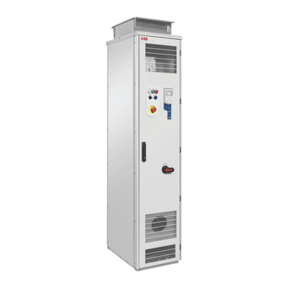
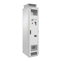
ABB ACQ580-07 Electrical Planning Instructions (36 pages)
Single drive cabinets and modules
Brand:
ABB
| Category:
Control Unit
| Size: 1.06 MB
Table of Contents
Table of Contents
5
1 Introduction to the Manual
7
Contents of this Chapter
7
Applicability
7
Target Audience
7
Terms and Abbreviations
7
Related Documents
8
ACS880 Single Drive Modules
8
ACS880 Single Drive Cabinets
8
ACS580, ACH580 and ACQ580 Drive Modules
8
AH580-07 and ACQ580-07 Cabinets
8
2 Electrical Planning Guidelines
11
Contents of this Chapter
11
Limitation of Liability
11
Selecting the Supply Disconnecting Device
11
Cabinets
11
Modules
11
European Union
11
North America
12
Other Regions
12
Selecting the Main Contactor (Breaker)
12
Cabinets
12
Modules
12
Examining the Compatibility of the Motor and Drive
12
Protecting the Motor Insulation and Bearings
13
Requirements Table
13
Availability of Du/Dt Filter and Common Mode Filter by Drive Type
15
Additional Requirements for Explosion-Safe (EX) Motors
16
And am
16
Additional Requirements for Braking Applications
16
Additional Requirements for the Regenerative and Low Harmonics Drives
16
Additional Requirements for ABB High-Output and IP23 Motors
16
Additional Requirements for Non-ABB High-Output and IP23 Motors
16
Additional Data for Calculating the Rise Time and the Peak Line-To-Line Voltage
17
Additional Note for Sine Filters
19
Selecting the Power Cables
19
General Guidelines
19
Typical Power Cable Sizes
20
Power Cable Types
21
Preferred Power Cable Types
21
Alternate Power Cable Types
21
Not Allowed Power Cable Types
22
Additional Guidelines, North America
22
Metal Conduit
23
Power Cable Shield
23
Selecting the Control Cables
23
Shielding
23
Signals in Separate Cables
24
Signals that Can be Run in the same Cable
24
Relay Cable Type
24
Control Panel to Drive Cable
24
Routing the Cables
24
General Guidelines - IEC
24
General Guidelines - North America
25
Continuous Motor Cable Shield/Conduit or Enclosure for Equipment on the Motor Cable
26
Separate Control Cable Ducts
27
Implementing Motor Temperature Sensor Connection
27
Connecting Motor Temperature Sensor to the Drive Via an Option Modules
27
Connection of Motor Temperature Sensor to the Drive Via a Relay
28
Implementing a Ground Fault Detection Function
29
Residual Current Device Compatibility
29
Implementing the Emergency Stop Function
29
Cabinets
29
Modules
29
Implementing the Safe Torque off Function
30
Implementing the Prevention of Unexpected Start-Up Function
30
ACS880 Cabinets
30
Modules
30
Implementing the Functions Provided by the FSO-XX Safety Functions Module
30
ACS880 Single Drive Cabinets
30
Supplying Power for the Auxiliary Circuits
31
Cabinets
31
Modules
31
Using Power Factor Compensation Capacitors with the Drive
31
Using a Safety Switch between the Drive and the Motor
31
Implementing the ATEX-Certified Safe Motor Disconnection Function (Option +Q971)
31
Implementing the Power-Loss Ride-Through Function
32
Cabinets with Line Contactor (Option +F250)
32
Implementing the Control of a Contactor between Drive and Motor
32
Acs880
32
ACS580, ACH580 and ACQ580
33
Implementing a Bypass Connection
33
Protecting the Contacts of Relay Outputs
33
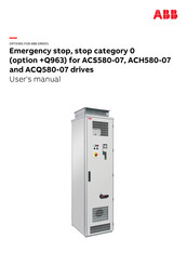
ABB ACQ580-07 User Manual (40 pages)
Emergency stop, stop category 0
Brand:
ABB
| Category:
Industrial Equipment
| Size: 0.65 MB
Table of Contents
Table of Contents
5
Safety Instructions
7
Contents of this Chapter
7
Use of Warnings and Notes
7
Instructions for Functional Safety Circuits
8
Electrical Safety Precautions
9
Introduction to the Manual
11
Contents of this Chapter
11
Applicability
11
Target Audience
11
Exclusion of Liability
12
Quick Reference Guide for Taking a Safety Function into Use
12
Related Manuals
12
Terms and Abbreviations
13
Option Description
15
Contents of this Chapter
15
Overview
15
Operation Principle
16
Fault Reaction Function
17
Hardware Settings
17
Electrical Installation
19
Contents of this Chapter
19
Wiring
19
Parameter Settings
21
Contents of this Chapter
21
Drive Parameter Settings
21
Use of the Safety Function
23
Contents of this Chapter
23
Activating the Safety Function
23
Resetting the Safety Function
23
Start-Up and Validation Test
25
Contents of this Chapter
25
Validation of the Safety Functions
25
Competence
25
Validation Procedure
25
Validation Test Reports
26
Start-Up and Validation Test
26
Fault Tracing
29
Contents of this Chapter
29
Reporting Problems and Failures Related to Safety Functions
30
Maintenance
31
Contents of this Chapter
31
Safety Circuit Maintenance
31
Proof Test Interval
31
Functional Safety Components
32
Competence
32
Residual Risk
32
Intentional Misuse
32
Decommissioning
33
Technical Data
35
Contents of this Chapter
35
Safety Data
35
Safety Data Values
35
Safety Component Types
36
Safety Block Diagrams
36
Relevant Failure Modes
36
Fault Exclusions
36
Operation Delays
36
Ambient Conditions
36
Related Standards and Directives
36
Compliance with the European Machinery Directive
37
Compliance with the Supply of Machinery (Safety) Regulations (UK)
37
Further Information
39
Advertisement
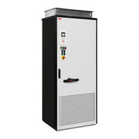
ABB ACQ580-07 User Manual (36 pages)
Emergency stop, stop category 0 (option +Q951)
Brand:
ABB
| Category:
Controller
| Size: 0.61 MB
Table of Contents
List of Related Manuals
2
Table of Contents
5
1 Introduction to the Manual
7
Contents of this Chapter
7
Applicability
7
Safety Instructions
7
Target Audience
8
Contents
8
Related Documents
8
Abbreviations
8
Exclusion of Liability
9
Quick Reference Guide for Implementing a Safety System
10
2 Option Description and Instructions
11
Contents this Chapter
11
Overview
11
Operation Principle
12
ACS880-07 Drives, Frames R6 to R11 and ACS880-17/-37 Drives, Frame R8
12
ACS880-17/37 Drives, Frame R11
13
ACS880-07 Drives, Frames Nxdxt + Nxr8I
14
ACS880-17/37 Drives, Frames Nxr8I + Nxr8I
15
Fault Reaction Function
16
Parameter Settings
16
Hardware Settings
17
Wiring
17
Start-Up and Acceptance Test
18
Checks and Settings with no Voltage Connected
18
Settings with Voltage Connected
18
Acceptance Test
18
Use of the Safety Function
20
Activating
20
Resetting
20
Emergency Stop Indications
20
Fault Tracing
20
Maintenance
21
Proof Test Interval
21
Competence
21
Residual Risk
21
Intentional Misuse
22
Decommissioning
22
Safety Data
23
Safety Data Values
23
ACS880-07 Drives with a Main Contactor
24
ACS880-17/37 Drives with a Main Contactor
26
ACS880-07/17/37 Drives with a Main Circuit Breaker
28
Safety Component Types
28
Safety Block Diagrams
29
Relevant Failure Modes
30
Fault Exclusions
30
Operation Delays
30
General Rules, Notes and Definitions
31
Validation of the Safety Functions
31
Validation Procedure
31
Acceptance Test Reports
31
Competence
31
Ambient Conditions
32
ACS880-07 Drives, Frames R6 to R11
32
Reporting Problems and Failures Related to Safety Functions
32
Related Standards and Directives
33
Compliance with the European Machinery Directive
33
Further Information
35
Product and Service Inquiries
35
Product Training
35
Providing Feedback on ABB Drives Manuals
35
Document Library on the Internet
35
Advertisement
Related Products
ABB ACQ580
ABB ACQ80-04-0kW75-4
ABB ACQ80-04-01kW1-4
ABB ACQ80-04-01kW5-4
ABB ACQ80-04-05kW5-4
ABB ACQ80-04-011kW-4
ABB ACQ80-04-015kW-4
ABB ACQ80-04-037kW-4
ABB ACQ80-04-055kW-4
ABB ACQ80-04-045kW-4
ABB Categories
Industrial Equipment
Controller
Measuring Instruments
Battery Charger
DC Drives
More ABB Manuals
Login
Sign In
OR
Sign in with Facebook
Sign in with Google
Upload manual
Upload from disk
Upload from URL