Sign In
Upload
Manuals
Brands
ABB Manuals
DC Drives
ACS850-04 series
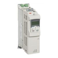
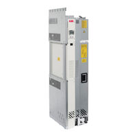
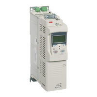
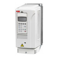
ABB ACS850-04 series Manuals
Manuals and User Guides for ABB ACS850-04 series. We have
13
ABB ACS850-04 series manuals available for free PDF download: Firmware Manual, Quick Start Up Manual, Hardware Manual, Quick Installation Manual, Application Manual, Manual
ABB ACS850-04 series Firmware Manual (296 pages)
Standard Control Program
Brand:
ABB
| Category:
Control Unit
| Size: 4.58 MB
Table of Contents
ACS850 Drive Manuals
2
Table of Contents
5
About the Manual
11
What this Chapter Contains
11
Compatibility
11
Safety Instructions
11
Reader
11
Contents
12
Related Manuals
12
The ACS850 Control Panel
13
What this Chapter Contains
13
Features
13
Installation
14
Mechanical Installation
14
Electrical Installation
14
Layout
15
Status Line
16
Operating Instructions
17
Basics of Operation
17
List of Tasks
18
Help and Panel Version - any Mode
19
Basic Operations - any Mode
20
Output Mode
21
Parameters
23
Assistants
30
Changed Parameters
32
Fault Logger
34
Time & Date
36
Parameter Backup
38
I/O Settings
46
Reference Edit
48
Drive Info
49
Parameter Change Log
50
Control Locations and Operating Modes
53
What this Chapter Contains
53
Local Control Vs. External Control
54
Local Control
54
External Control
55
Operating Modes of the Drive
55
Speed Control Mode
55
Torque Control Mode
55
Special Control Modes
55
Program Features
57
What this Chapter Contains
57
Application Macros
58
Automatic Fault Resets
58
Autophasing
58
Constant Speeds
59
Critical Speeds
59
DC Voltage Control
59
Overvoltage Control
59
Undervoltage Control
60
Voltage Control and Trip Limits
60
Brake Chopper
61
Drive-To-Drive Link
61
Emergency Stop
62
Encoder Support
62
Energy Optimizer
62
Fieldbus Control
63
Jogging
63
Load Analyzer
64
Peak Value Logger
64
Amplitude Loggers
64
Maintenance Counters
65
Mechanical Brake Control
66
Process PID Control
70
Sleep Function for Process PID Control
70
Programmable Analog Inputs
71
Programmable Analog Outputs
72
Programmable Digital Inputs and Outputs
72
Programmable Relay Outputs
72
Programmable Protection Functions
72
Start Interlock (Parameter 10.20)
72
External Fault (Parameter 30.01)
73
Local Control Loss Detection (Parameter 30.03)
73
Motor Phase Loss Detection (Parameter 30.04)
73
Earth Fault Detection (Parameter 30.05)
73
Supply Phase Loss Detection (Parameter 30.06)
73
Safe Torque off Detection (Parameter 30.07)
73
Switched Supply and Motor Cabling (Parameter 30.08)
73
Stall Protection (Parameters 30.09
73
Scalar Motor Control
74
IR Compensation for a Scalar Controlled Drive
74
Signal Supervision
74
Speed Controller Tuning
74
Thermal Motor Protection
76
Thermal Motor Protection Model
76
Temperature Measurement
76
Settings
77
Timers
77
User-Definable Load Curve
79
User-Definable U/F Curve
79
Advertisement
ABB ACS850-04 series Hardware Manual (164 pages)
drive modules (160 to 560 kW, 200 to 700 hp)
Brand:
ABB
| Category:
DC Drives
| Size: 22.03 MB
Table of Contents
Table of Contents
5
List of Related Manuals
2
Table of Contents
5
Table of Contents
12
Safety Instructions
13
What this Chapter Contains
13
Use of Warnings
13
Safety in Installation and Maintenance
14
Electrical Safety
14
Grounding
15
Permanent Magnet Motor Drives
16
General Safety
17
Fiber Optic Cables
18
Printed Circuit Boards
19
Safe Start-Up and Operation
19
General Safety
19
Permanent Magnet Motor Drives
19
Introduction to the Manual
21
What this Chapter Contains
21
Target Audience
21
Contents of the Manual
21
Categorization by Frame Size and Option Code
22
Quick Installation, Commissioning and Operating Flowchart
22
Terms and Abbreviations
24
Operation Principle and Hardware Description
27
What this Chapter Contains
27
Product Overview
27
Layout
28
Power Connections and Control Interfaces
32
External Control Unit Connection Cables
33
Type Designation Label
34
Type Designation Key
35
Planning the Cabinet Installation
37
What this Chapter Contains
37
Limitation of Liability
37
Basic Requirements for the Cabinet
37
Planning the Layout of the Cabinet
37
Layout Example, Door Open
38
Layout Examples, Door Closed
38
Arranging the Grounding Inside the Cabinet
40
Selecting the Busbar Material and Preparation of the Joints
40
Tightening Torques
40
Planning the Fastening of the Cabinet
40
Planning the Cabinet Placement on a Cable Channel
41
Planning the Electromagnetic Compatibility (EMC) of the Cabinet
41
Planning the Grounding of the Cable Shields at the Cabinet Lead-Through
43
Planning the Cooling
43
Preventing the Recirculation of Hot Air
45
Required Free Space
47
Free Space Around the Drive Module
47
Free Space at the Top of the Drive Module
47
Other Installation Positions
47
Planning the Placement of the Control Panel
48
Planning the Use of the Cubicle Heaters
48
Planning the Electrical Installation
49
What this Chapter Contains
49
Selecting the Supply Disconnecting Device
49
European Union
49
Other Regions
49
Selecting and Dimensioning the Main Contactor
49
Protecting the Motor Insulation and Bearings
50
Checking the Compatibility of the Motor and Drive
50
Requirements Table
51
Additional Requirements for ABB High-Output Motors and IP23 Motors
53
Additional Requirements for Explosion-Safe (EX) Motors
53
Additional Requirements for HXR and AMA Motors
53
Additional Requirements for the Braking Applications
53
And am
53
Additional Requirements for Non-ABB High-Output and IP23 Motors
54
Additional Data for Calculating the Rise Time and the Peak Line-To-Line Voltage
55
Additional Note Common Mode Filters
55
Additional Note for Sine Filters
55
Selecting the Power Cables
56
General Rules
56
Typical Power Cable Sizes
57
Alternative Power Cable Types
58
Motor Cable Shield
58
Additional US Requirements
59
Armored Cable / Shielded Power Cable
59
Conduit
59
Selecting the Control Cables
59
Shielding
59
Control Panel Cable Length and Type
60
Relay Cable Type
60
Signals Allowed to be Run in the same Cable
60
Signals in Separate Cables
60
Routing the Cables
60
Separate Control Cable Ducts
61
Continuous Motor Cable Shield or Enclosure for Equipment in the Motor Cable
62
Implementing Thermal Overload and Short-Circuit Protection
62
Protecting the Drive and Input Power Cable in Short-Circuits
62
Protecting the Motor and Motor Cable in Short-Circuits
62
Protecting the Drive and the Input Power and Motor Cables against Thermal Overload
63
Protecting the Motor against Thermal Overload
63
Protecting the Drive against Ground Faults
63
Residual Current Device Compatibility
63
Implementing the Emergency Stop Function
64
Implementing the Safe Torque off Function
64
Implementing the ATEX-Certified Safe Motor Disconnection Function (Option +Q971)
64
Implementing the Power Loss Ride-Through Function
64
Using Power Factor Compensation Capacitors with the Drive
64
Implementing a Safety Switch between the Drive and Motor
65
Using a Contactor between the Drive and the Motor
65
Implementing a Bypass Connection
66
Example Bypass Connection
66
Switching the Motor Power Supply from Direct-On-Line to Drive
67
Switching the Motor Power Supply from Drive to Direct-On-Line
67
Protecting the Contacts of Relay Outputs
67
Connecting a Motor Temperature Sensor to the Drive I/O
68
Example Circuit Diagram
68
Installation
69
What this Chapter Contains
69
Safety
73
Checking the Installation Site
73
Required Tools
73
Moving and Unpacking the Unit
74
Checking the Delivery
76
Checking the Insulation of the Assembly
76
Drive
76
Input Cable
76
Brake Resistor and Resistor Cable
77
Motor and Motor Cable
77
Overall Flowchart of the Installation Process
78
Installing the Mechanical Accessories into the Cabinet
79
Assembly Drawing (Frame G1)
81
Assembly Drawing (Frame G2)
82
Assembly Drawing (Air Baffles)
83
Connecting the Power Cables
84
Connection Diagram
84
Power Cable Connection Procedure
86
DC Connection
88
Mounting the Drive Module into the Cabinet
89
Mounting Procedure
90
Assembly Drawing of Installing the Drive Module to the Cabinet (Frame G1)
93
Assembly Drawing of Installing the Drive Module to the Cabinet (Frame G2)
94
Removing the Protective Covering from the Module Air Outlet
95
Connecting the Control Cables
95
Flowchart of the Control Cable Installation Process (External Control Unit)
95
Flowchart of the Control Cable Installation Process (Internal Control Unit, Option +P905)
95
Removing the Cover Assembly of the External Control Unit
96
Connecting the External Control Unit to the Drive Module
97
Fastening the Control Cable Clamp Plate
97
Mounting the External Control Unit
99
Mounting the External Control Unit to Wall
99
Mounting the Control Unit Horizontally on a DIN Rail
100
Mounting the External Control Unit Vertically on a DIN Rail
100
Installing Optional Modules
101
Mechanical Installation
101
Wiring the Modules
101
Connecting the Control Cables to the Terminals of the Control Unit
102
Default I/O Connection Diagram
104
Jumpers
105
DI6 (XDI:6) as a Thermistor Input
106
External Power Supply for the JCU Control Unit (XPOW)
106
Drive-To-Drive Link (XD2D)
107
Safe Torque off (XSTO)
108
Control Cable Connection Procedure of Units with Internal Control Unit (Option +P905)
108
Connecting a PC
108
Installation Checklist
109
What this Chapter Contains
109
Start-Up
113
What this Chapter Contains
113
Start-Up Procedure
113
Fault Tracing
115
What this Chapter Contains
115
Leds
115
Warning and Fault Messages
115
Maintenance
117
What this Chapter Contains
117
Applicability
117
Maintenance Intervals
117
Cabinet
118
Cleaning the Interior of the Cabinet
118
Heatsink
119
Cleaning the Interior of the Heatsink
119
Fans
120
Replacing the Circuit Board Compartment Cooling Fan
120
Replacing the Main Cooling Fans
121
Replacing the Drive Module
122
Capacitors
124
Reforming the Capacitors
124
Memory Unit
124
Technical Data
125
What this Chapter Contains
125
Ratings
125
Altitude Derating
126
Ambient Temperature Derating
126
Derating
126
Fuses (IEC)
127
Ar Fuses with Flush End Contact
127
Ultrarapid (Ar) Fuses
127
Fuses (UL)
127
UL Recognised Class T / Class L Fuses
127
Dimensions, Weights and Free Space Requirements
128
Losses, Cooling Data and Noise
129
Terminal and Lead-Through Data for the Power Cables
129
Units with Optional Cabling Panels (+H381 or +H383)
129
Units with Optional Common Mode Filter (+E208)
129
Units Without Optional Cabling Panels (no +H381 or +H383)
130
Terminal Data for the Control Cables
130
Electrical Power Network Specification
130
Motor Connection Data
130
Brake Resistor Connection Data
130
DC Connection Data
131
Control Unit (JCU-11) Connection Data
131
Efficiency
133
Degree of Protection
133
Ambient Conditions
134
Materials
135
Applicable Standards
135
CE Marking
136
Compliance with the European EMC Directive
136
Compliance with the European Low Voltage Directive
136
Compliance with the European Machinery Directive
136
Compliance with en 61800-3:2004
136
Definitions
136
Category C3
137
Category C4
137
UL Marking
138
UL Checklist
138
CSA Marking
138
C-Tick" Marking
138
GOST R Certificate of Conformity
138
Disclaimer
139
Dimension Drawings
141
What this Chapter Contains
141
Frame G1 - Drive Module Dimensions
142
Frame G1 - Drive Module Dimensions with Optional Cabling Panels (+H381)
143
Frame G1 - Cabling Panels (+H383) Installed into a Rittal TS 8 Cabinet
145
Frame G2 - Drive Module Dimensions
146
Frame G2 - Drive Module Dimensions with Optional Cabling Panels (+H381)
147
Frame G2 - Cabling Panels (+H383) Installed into a Rittal TS 8 Cabinet
149
Frames G1 and G2 - Bottom Plate
150
Frames G1 and G2 - Air Baffles
151
Example Circuit Diagram
153
What this Chapter Contains
153
Example Circuit Diagram
154
Resistor Braking
155
What this Chapter Contains
155
Availability of Brake Choppers and Resistors
155
When Is Resistor Braking Needed
155
Operation Principle
155
Planning the Braking System
155
Selecting the Brake Circuit Components
155
Placing the Brake Resistors
156
Minimizing Electromagnetic Interference
157
Protecting the System in Fault Situations
157
Selecting and Routing the Brake Circuit Cables
157
Short-Circuit Protection
157
Thermal Overload Protection
157
EMC Compliance of the Complete Installation
158
Maximum Cable Length
158
Mechanical Installation
158
Electrical Installation
158
Connection Diagram
158
Connection Procedure
158
Brake Circuit Commissioning
158
Technical Data
159
Brake Resistor Connection Data
159
Maximum Resistor Cable Length
159
Ratings
159
SAFUR Resistors
159
Dimensions and Weights
160
What this Chapter Contains
161
Product and Service Inquiries
163
ABB ACS850-04 series Hardware Manual (145 pages)
Drive Modules
Brand:
ABB
| Category:
DC Drives
| Size: 7.2 MB
Table of Contents
Table of Contents
5
List of Related Manuals
2
Table of Contents
5
Table of Contents
12
Safety Instructions
13
What this Chapter Contains
13
Use of Warnings
13
Safety in Installation and Maintenance
14
Electrical Safety
14
Grounding
15
Permanent Magnet Motor Drives
16
General Safety
17
Fiber Optic Cables
18
Printed Circuit Boards
18
Safe Start-Up and Operation
19
General Safety
19
Permanent Magnet Motor Drives
19
Introduction to the Manual
21
What this Chapter Contains
21
Target Audience
21
Contents of the Manual
21
Categorization by Option Code
22
Quick Installation, Commissioning and Operating Flowchart
22
Terms and Abbreviations
24
Operation Principle and Hardware Description
25
What this Chapter Contains
25
What the ACS850-04 Is
25
Product Overview
26
Layout
26
Alternative Output Busbar Configurations
28
Control Unit Variants
28
Component Placement
29
Power Connections and Control Interfaces
30
Cables for Connecting the Control Unit to the Drive Module and Control Panel
31
Circuit Boards
31
Type Designation Label
32
Type Designation Key
32
Planning the Cabinet Installation
35
What this Chapter Contains
35
Basic Requirements for the Cabinet
35
Planning the Layout of the Cabinet
36
Layout Examples, Door Closed
36
Layout Examples, Door Open
37
Arranging the Grounding Inside the Cabinet
38
Selecting Busbar Material and Preparation of the Joints
38
Tightening Torques
38
Planning the Fastening of the Cabinet
38
Planning the Cabinet Placement on a Cable Channel
39
Planning the Electro Magnetic Compatibility (EMC) of the Cabinet
39
Planning the Grounding of the Cable Shields at the Cabinet Lead-Through
41
Planning the Cooling
41
Preventing the Recirculation of Hot Air
43
Prevention the Air Recirculation Inside the Cabinet
43
Prevention the Air Recirculation Outside the Cabinet
43
Required Free Space Around the Drive Module
43
Free Space at Top with High Air Inlet Gratings in the Cabinet Door
44
Free Space at Top with Low Air Inlet Gratings in the Cabinet Door
44
Free Space at the Side and Front of the Drive Module
45
Other Installation Positions
45
Planning the Placement of the Control Panel
46
Planning the Use of the Cubicle Heaters
46
Mechanical Installation
47
What this Chapter Contains
47
Safety
47
Checking the Installation Site
48
Required Tools
48
Moving and Unpacking the Unit
48
Checking the Delivery
49
Attaching the Warning Stickers
49
Fastening the Cable Lug Terminals to the Output Busbars
50
Fastening the Drive Module to the Cabinet Base
52
Installing the Drive Control Unit
53
Mounting through the Fastening Holes
53
Vertical DIN Rail Mounting
54
Horizontal DIN Rail Mounting
55
Planning the Electrical Installation
57
What this Chapter Contains
57
Selecting the Supply Disconnecting Device (Disconnecting Means)
57
European Union
57
Other Regions
57
Selecting and Dimensioning the Main Contactor
57
Checking the Compatibility of the Motor and Drive
58
Protecting the Motor Insulation and Bearings
58
Requirements Table
59
Selecting the Power Cables
62
General Rules
62
Typical Power Cable Sizes
63
Typical Power Cable Sizes (US)
64
Additional US Requirements
65
Alternative Power Cable Types
65
Motor Cable Shield
65
Armored Cable / Shielded Power Cable
66
Conduit
66
Selecting the Control Cables
66
Shielding
66
Control Panel Cable Length and Type
67
Relay Cable Type
67
Signals Allowed to be Run in the same Cable
67
Signals in Separate Cables
67
Routing the Cables
67
Diagram
68
Separate Control Cable Ducts
68
Continuous Motor Cable Shield or Enlosure for Equipment in the Motor Cable
69
Implementing Thermal Overload and Short-Circuit Protection
69
Protecting the Drive and Input Power Cable in Short-Circuits
69
Protecting the Drive and the Input Power and Motor Cables against Thermal Overload
70
Protecting the Motor against Thermal Overload
70
Protecting the Motor and Motor Cable in Short-Circuits
70
Protecting the Drive against Ground Faults
71
Residual Current Device Compatibility
71
Implementing the Emergency Stop Function
71
Implementing the Safe Torque off Function
71
Implementing the Power-Loss Ride-Through Function
72
Using Power Factor Compensation Capacitors with the Drive
73
Implementing a Safety Switch between the Drive and Motor
73
Using a Contactor between the Drive and the Motor
73
Implementing a Bypass Connection
74
Protecting the Contacts of Relay Outputs
75
Connecting a Motor Temperature Sensor to the Drive I/O
76
Example Circuit Diagram
76
Electrical Installation
77
What this Chapter Contains
77
Warnings
77
Checking the Insulation of the Assembly
77
Drive
77
Input Cable
77
Motor and Motor Cable
77
Brake Resistor and Resistor Cable
78
Checking the Combatibility with IT (Ungrounded) and TN (Corner Grounded) Systems
78
Connecting the Power Cables
79
Connection Diagram
79
Input Cable Connection Procedure
80
Removing the Protective Covering
80
Motor Cable Connection Procedure
81
DC Connection
82
Checking the Settings of the Cooling Fan Transformer
82
Removing the Cover Assembly
83
Fastening the Control Cable Clamp Plate
84
Grounding the Control Unit
84
Connecting the Control Unit to the Drive Module
85
Connecting the Control Cables
86
Default I/O Connection Diagram
87
Jumpers
88
DI6 (XDI:6) as a Thermistor Input
89
External Power Supply for the JCU Control Unit (XPOW)
89
Drive-To-Drive Link (XD2D)
90
Control Cable Connection Procedure
91
Safe Torque off (XSTO)
91
Routing the Control Cables
92
Connecting a PC
93
Installing Optional Modules
93
Mechanical Installation
93
Wiring the Modules
93
Installation Checklist
95
What this Chapter Contains
95
Mechanical Installation
95
Cabinet Construction
95
Instrumentation, Busbars and Cabling
95
Groundings and Protection
97
Labels, Switches, Fuses and Doors
97
Electrical Installation
97
Cooling and Driven Equipment
98
Start-Up
99
What this Chapter Contains
99
Start-Up Procedure
99
Fault Tracing
101
What this Chapter Contains
101
Leds
101
Warning and Fault Messages
101
What this Chapter Contains
103
Maintenance Intervals
103
Cabinet
103
Heatsink
104
Fan
104
Replacing the Cooling Fan of the Module
105
Replacing the Drive Module
106
Capacitors
108
Reforming the Capacitors
108
Replacing the Capacitor Pack
109
Memory Unit
110
Technical Data
111
What this Chapter Contains
111
Ratings
111
Derating
111
Altitude Derating
112
Ambient Temperature Derating
112
Fuses (IEC)
112
Calculation Example
113
Fuse Tables
114
Gg Fuses
114
Ultrarapid (Ar) Fuses
114
Quick Guide for Selecting between Gg and Ar Fuses
115
Fuses (UL)
115
UL Class T and L Fuses
116
Dimensions, Weights and Free Space Requirements
116
Losses, Cooling Data and Noise
117
IP22 Cabinet with no Extra Fan
117
IP54 Cabinet with an Extra Fan
117
Terminal and Lead-Through Data for the Power Cables
118
Terminal Data for the Control Cables
118
Electrical Power Network Specification
118
Motor Connection Data
118
Brake Resistor Connection Data
119
Control Unit (JCU-11) Connection Data
119
Efficiency
121
Degree of Protection
121
Ambient Conditions
122
Materials
123
Applicable Standards
123
CE Marking
124
Compliance with the European EMC Directive
124
Compliance with the European Low Voltage Directive
124
Compliance with the European Machinery Directive
124
C-Tick" Marking
124
Compliance with the en 61800-3:2004
124
Definitions
124
Category C3
125
Category C4
125
UL Marking
126
UL Checklist
126
CSA Marking
126
Patent Protection in the USA
126
Dimension Drawings
127
What this Chapter Contains
127
Frame Size G Without Pedestal (MM)
127
Frame Size G with Busbars on the Left Side (MM)
128
Frame Size G Pedestal Busbars on the Long Side (MM)
129
Drive Control Unit (JCU)
130
Package
131
Dimension Drawings (USA)
132
Frame Size G Without Pedestal (Inches)
132
Frame Size G with Busbars on the Left Side (Inches)
133
Frame Size G Pedestal Busbars on the Long Side (Inches)
134
Example Circuit Diagrams
135
What this Chapter Contains
135
Example Circuit Diagram
136
Resistor Braking
137
What this Chapter Contains
137
Availability of Brake Choppers and Resistors
137
When Is Resistor Braking Needed
137
Operation Principle
137
Hardware Description
137
Planning the Braking System
137
Selecting the Brake Circuit Components
137
Placing the Brake Resistors
138
Protecting the System in Fault Situations
139
Selecting and Routing the Brake Circuit Cables
139
Short-Circuit Protection
139
Thermal Overload Protection
139
Cable Length
140
EMC Compliance of the Complete Installation
140
Minimizing Electromagnetic Interference
140
Mechanical Installation
140
Electrical Installation
140
Brake Circuit Commissioning
140
Technical Data
141
Brake Resistor Connection Data
142
What this Chapter Contains
143
Product and Service Inquiries
145
Advertisement
ABB ACS850-04 series Hardware Manual (147 pages)
Drive Modules (400 to 560 kW, 450 to 700 hp)
Brand:
ABB
| Category:
DC Drives
| Size: 12.75 MB
Table of Contents
List of Related Manuals
6
Table of Contents
9
Table of Contents
15
Safety Instructions
15
What this Chapter Contains
15
Use of Warnings
15
Safety in Installation and Maintenance
16
Electrical Safety
16
Grounding
17
Permanent Magnet Motor Drives
18
General Safety
19
Fiber Optic Cables
20
Printed Circuit Boards
21
Safe Start-Up and Operation
21
General Safety
21
Permanent Magnet Motor Drives
21
Introduction to the Manual
23
What this Chapter Contains
23
Target Audience
23
Contents of the Manual
23
Categorization by Option Code
24
Quick Installation, Commissioning and Operating Flowchart
24
Terms and Abbreviations
26
Operation Principle and Hardware Description
29
What this Chapter Contains
29
Product Overview
29
Layout
30
Power Connections and Control Interfaces
34
External Control Unit Connection Cables
35
Type Designation Label
35
Type Designation Key
36
Planning the Cabinet Installation
39
What this Chapter Contains
39
Basic Requirements for the Cabinet
39
Planning the Layout of the Cabinet
39
Layout Examples, Door Closed
40
Layout Examples, Door Open
41
Arranging the Grounding Inside the Cabinet
42
Selecting the Busbar Material and Preparation of the Joints
42
Tightening Torques
42
Planning the Fastening of the Cabinet
42
Planning the Cabinet Placement on a Cable Channel
43
Planning the Electromagnetic Compatibility (EMC) of the Cabinet
43
Planning the Grounding of the Cable Shields at the Cabinet Lead-Through
45
Planning the Cooling
45
Preventing the Recirculation of Hot Air
47
Required Free Space
47
Free Space at Top with Air Inlet Gratings in the Cabinet Door
48
Free Space Around the Drive Module
48
Other Installation Positions
48
Planning the Placement of the Control Panel
48
Planning the Use of the Cubicle Heaters
49
Planning the Electrical Installation
51
What this Chapter Contains
51
Selecting the Supply Disconnecting Device (Disconnecting Means)
51
European Union
51
Other Regions
51
Selecting and Dimensioning the Main Contactor
51
Protecting the Motor Insulation and Bearings
52
Checking the Compatibility of the Motor and Drive
52
Requirements Table
53
Explosion-Safe (EX) Motors
54
High-Output Motors and IP 23 Motors
55
HXR and AMA Motors
55
ABB Motors of Types Other than M2_, M3_, HX_ and am
55
Resistor Braking of the Drive
55
Calculating the Rise Time and the Peak Line-To-Line Voltage
55
Sine Filters
56
Common Mode Filters
56
Selecting the Power Cables
56
General Rules
56
Typical Power Cable Sizes
57
Typical Power Cable Sizes (US)
58
Alternative Power Cable Types
58
Motor Cable Shield
59
Additional US Requirements
59
Conduit
59
Armored Cable / Shielded Power Cable
59
Selecting the Control Cables
60
Shielding
60
Signals in Separate Cables
60
Signals Allowed to be Run in the same Cable
60
Relay Cable Type
60
Control Panel Cable Length and Type
60
Routing the Cables
60
Separate Control Cable Ducts
62
Continuous Motor Cable Shield or Enlosure for Equipment in the Motor Cable
62
Implementing Thermal Overload and Short-Circuit Protection
63
Protecting the Drive and Input Power Cable in Short-Circuits
63
Protecting the Motor and Motor Cable in Short-Circuits
63
Protecting the Drive and the Input Power and Motor Cables against Thermal Overload
64
Protecting the Motor against Thermal Overload
64
Protecting the Drive against Ground Faults
64
Residual Current Device Compatibility
64
Implementing the Emergency Stop Function
65
Implementing the Safe Torque off Function
65
Implementing the ATEX-Certified Safe Motor Disconnection Function (Option +Q971)
67
Implementing the Power Loss Ride-Through Function
67
Using Power Factor Compensation Capacitors with the Drive
67
Implementing a Safety Switch between the Drive and Motor
68
Using a Contactor between the Drive and the Motor
68
Implementing a Bypass Connection
68
Example Bypass Connection
69
Switching the Motor Power Supply from Drive to Direct-On-Line
70
Switching the Motor Power Supply from Direct-On-Line to Drive
70
Protecting the Contacts of Relay Outputs
70
Connecting a Motor Temperature Sensor to the Drive I/O
71
Example Circuit Diagram
71
ABB ACS850-04 series Hardware Manual (132 pages)
Drive modules 0.37 to 45 kW, 0.5 to 60 hp
Brand:
ABB
| Category:
DC Drives
| Size: 5.24 MB
Table of Contents
List of Related Manuals
2
Safety Instructions
5
What this Chapter Contains
5
Use of Warnings and Notes
5
Installation and Maintenance Work
6
Start-Up and Operation
8
Table of Contents
9
Table of Contents
15
Introduction to this Manual
15
What this Chapter Contains
15
Compatibility
15
Intended Audience
15
Categorization According to the Frame Size
15
Categorization According to the + Code
15
Contents
15
Installation and Commissioning Flowchart
17
Terms and Abbreviations
19
Operation Principle and Hardware Description
21
What this Chapter Contains
21
Operation Principle
21
Main Circuit
21
Motor Control
22
Product Overview
22
Layout
23
Power Connections and Control Interfaces
24
Type Designation Label
25
Type Designation Key
26
Planning the Cabinet Assembly
29
What this Chapter Contains
29
Cabinet Construction
29
Disposition of the Devices
29
Grounding of Mounting Structures
29
Main Dimensions and Free Space Requirements
30
Cooling and Degrees of Protection
31
Preventing the Recirculation of Hot Air
33
Outside the Cabinet
33
Inside the Cabinet
33
Cabinets with Multiple Modules
34
Cabinet Heaters
35
Mechanical Installation
37
Contents of the Package
37
Delivery Check and Drive Module Identification
39
Before Installation
39
Requirements for the Installation Site
39
Installation Procedure
40
Direct Surface Mounting
40
DIN Rail Mounting (Frames a and B Only)
40
Mains Choke Installation
41
EMC Filter Installation
41
Brake Resistor Installation
41
Planning the Electrical Installation
43
What this Chapter Contains
43
Motor Selection
43
Supply Disconnecting Device
43
Europe
43
Other Regions
43
Thermal Overload and Short Circuit Protection
44
Thermal Overload Protection
44
Protection against Short-Circuit in the Motor Cable
44
Protection against Short-Circuit in the Supply Cable or the Drive
44
Operating Time of the Fuses and Circuit Breakers
44
Circuit Breakers
44
Motor Thermal Protection
45
Ground Fault Protection
45
Emergency Stop Devices
45
Safe Torque off Function
46
Selecting the Power Cables
46
General Rules
46
Alternative Power Cable Types
47
Not Allowed Power Cable Type
47
Motor Cable Shield
48
Protecting the Relay Output Contacts and Attenuating Disturbances in Case of Inductive Loads
48
Considering the PELV Requirements at Sites above 2000 M (6562 Ft)
49
Selecting the Control Cables
50
Relay Cable
50
Control Panel Cable
50
Connection of a Motor Temperature Sensor to the Drive I/O
50
Routing the Cables
50
Control Cable Ducts
51
Electrical Installation
53
What this Chapter Contains
53
Removing the Cover Assembly
53
Checking the Insulation of the Assembly
55
Drive
55
Supply Cable
55
Motor and Motor Cable
55
Brake Resistor Assembly
55
Power Cable Connection
56
Power Cable Connection Diagram
56
Procedure
57
Grounding the Motor Cable Shield at the Motor End
58
Installation of Power Cable Clamp Plates
59
Power Cable Connection - Frame Size a
60
Power Cable Connection - Frame Size B
61
Power Cable Connection - Frame Sizes C and D (Connector Covers Removed)
62
DC Connection
63
Installation of Optional Modules
65
Mechanical Installation
65
Electrical Installation
65
Connecting the Control Cables
66
Control Connections to the JCU Control Unit
66
Jumpers
67
External Power Supply for the Control Unit (XPOW)
67
DI6 (XDI:6) as a Thermistor Input
68
Drive-To-Drive Link (XD2D)
69
Safe Torque off (XSTO)
70
Grounding and Routing the Control Cables
70
Installation Checklist
73
What this Chapter Contains
73
Checklist
73
Start-Up
75
What this Chapter Contains
75
Start-Up Procedure
75
ABB ACS850-04 series Hardware Manual (106 pages)
Drive Modules (55...160 kW, 75...200 hp)
Brand:
ABB
| Category:
Controller
| Size: 8.59 MB
Table of Contents
Safety Instructions
5
What this Chapter Contains
5
Use of Warnings and Notes
5
Installation and Maintenance Work
6
Start-Up and Operation
8
Table of Contents
9
Table of Contents
14
Table of Contents
15
About this Manual
15
What this Chapter Contains
15
Compatibility
15
Intended Audience
15
Categorization According to the Frame Size
15
Categorization According to the + Code
15
Contents
16
Installation and Commissioning Flowchart
17
Terms and Abbreviations
19
Product and Service Inquiries
20
Product Training
20
Providing Feedback on ABB Drives Manuals
20
Operation Principle and Hardware Description
21
What this Chapter Contains
21
The ACS850-04
21
Layout
21
Power Connections and Control Interfaces
22
Main Circuit and Operation
23
Type Code
24
Planning the Cabinet Assembly
27
What this Chapter Contains
27
Cabinet Construction
27
Disposition of the Devices
27
Grounding of Mounting Structures
27
Free Space Requirements
28
Cooling and Degrees of Protection
29
Preventing the Recirculation of Hot Air
30
Outside the Cabinet
30
Inside the Cabinet
30
Cabinet Heaters
31
EMC Requirements
31
Mechanical Installation
33
Contents of the Package
33
Delivery Check and Drive Module Identification
33
Before Installation
34
Requirements for the Installation Site
34
Connection to an IT (Ungrounded) or a Corner-Grounded Power System
34
Installation Procedure
34
Direct Wall Mounting
34
Braking Resistor Installation
34
Planning the Electrical Installation
35
What this Chapter Contains
35
Motor Selection and Compatibility
35
Protecting the Motor Insulation and Bearings
35
Permanent Magnet Synchronous Motors
35
Supply Connection
35
Supply Disconnecting Device
36
Europe
36
Other Regions
36
Thermal Overload and Short Circuit Protection
36
Thermal Overload Protection
36
Protection against Short-Circuit in Motor Cable
36
Protection against Short-Circuit in the Supply Cable or the Drive
36
Operating Time of the Fuses and Circuit Breakers
37
Circuit Breakers
37
Motor Thermal Protection
37
Ground Fault Protection
37
Emergency Stop Devices
37
Safe Torque off
38
Selecting the Power Cables
39
General Rules
39
Alternative Power Cable Types
40
Motor Cable Shield
40
Protecting the Relay Output Contacts and Attenuating Disturbances in Case of Inductive Loads
41
Selecting the Control Cables
41
Relay Cable
42
Control Panel Cable
42
Connection of a Motor Temperature Sensor to the Drive I/O
42
Routing the Cables
42
Control Cable Ducts
43
ABB ACS850-04 series Quick Start Up Manual (172 pages)
Standard Control Program
Brand:
ABB
| Category:
DC Drives
| Size: 2.13 MB
ABB ACS850-04 series Quick Installation Manual (109 pages)
Drive Modules (0.37 to 45 kW)
Brand:
ABB
| Category:
DC Drives
| Size: 26.02 MB
Table of Contents
ACS850 Drive Manuals
2
About this Guide
3
Safety Instructions
3
Removing the Cover Assembly
3
Mechanical Installation
3
Installing the Power Cables
5
Connection Diagram
5
Connection Procedure
6
Default I/O Connection Diagram
8
Technical Data
10
Om Denne Vejledning
11
Mekanisk Installation
11
Mechanische Installation
19
Diagrama de Conexiones
29
Procedimiento de Conexión
30
Pares de Apriete
31
Diagrama de Conexiones de E/S por Defecto
32
Datos Técnicos
34
Guide D'installation Rapide
35
Consignes de Sécurité
35
Montage
35
Schéma de Raccordement
37
Schéma de Raccordement des Signaux D'e/S (Préréglages)
40
Caractéristiques Techniques
42
Informazioni Sulla Guida
43
Installazione Meccanica
43
Schema DI Collegamento
45
Procedura DI Collegamento
46
Coppie DI Serraggio
47
Schema DI Collegamento Degli I/O DI Default
48
Dati Tecnici
50
Beknopte Installatiegids
51
Mechanische Installatie
51
Technische Gegevens
58
Guia de Instalação Rápida
59
Diagrama de Conexão
61
Dados Técnicos
66
Oletusarvoiset I/O-Ohjauskytkennät
72
Om Denna Guide
75
Mekanik Kurulum
83
Bağlantı Şeması
85
Teknik Veriler
90
Схема Подключения
93
Порядок Подключения
94
Стандартная Схема Подключения Входов/Выходов
96
Further Information
107
ABB ACS850-04 series Quick Installation Manual (83 pages)
Drive Modules (1.1 to 45 kW)
Brand:
ABB
| Category:
DC Drives
| Size: 15.29 MB
Table of Contents
ACS850 Drive Manuals
2
About this Guide
3
Safety Instructions
3
Installing the Power Cables
3
Mechanical Installation
3
Connection Procedure
4
Cabling Examples
5
Tightening Torques
5
Default I/O Connection Diagram
6
Technical Data
8
Om Denne Vejledning
9
Mekanisk Installation
9
Informationen über diese Anleitung
15
Mechanische Installation
15
Guía de Instalación Rápida
21
Instrucciones de Seguridad
21
Instalación Mecánica
21
Procedimiento de Conexión
22
Pares de Apriete
23
Diagrama de Conexiones de E/S por Defecto
24
Especificaciones Técnicas
26
Guide D'installation Rapide
27
Consignes de Sécurité
27
Montage
27
Exemples de Raccordement
29
Couples de Serrage
29
Schéma de Raccordement des Signaux D'e/S (Préréglages)
30
Caractéristiques Techniques
32
Procedura DI Collegamento
34
Coppie DI Serraggio
35
Schema DI Collegamento Degli I/O DI Default
36
Dati Tecnici
38
Beknopte Installatiegids
39
Mechanische Installatie
39
Technische Gegevens
44
Binários de Aperto
47
Dados Técnicos
50
Oletusarvoiset I/O-Ohjauskytkennät
54
Om Denna Guide
57
Mekanik Kurulum
63
Teknik Veriler
68
Схема Подключения
69
Механический Монтаж
69
Стандартная Схема Подключения Входов/Выходов
72
Технические Данные
74
ABB ACS850-04 series Quick Installation Manual (83 pages)
Drive Modules
Brand:
ABB
| Category:
Control Unit
| Size: 10.27 MB
Table of Contents
ACS850 Drive Manuals
2
About this Guide
3
Safety Instructions
3
Installing the Power Cables
3
Mechanical Installation
3
Connection Procedure
4
Cabling Examples
4
Wire Sizes Accepted by Power Terminals
5
Tightening Torques
5
Installing the Control Cables
6
Mounting the Clamp Plate
7
Technical Data
8
Om Denne Vejledning
9
Mekanisk Installation
9
Mechanische Installation
15
Anschluss der Steuerkabel
18
Standard E/A-Anschlüsse
18
Guía de Instalación Rápida
21
Procedimiento de Conexión
22
Pares de Apriete
23
Datos Técnicos
26
Mekaaninen Asennus
27
Oletusarvoiset I/O-Ohjauskytkennät
30
Guide D'installation Rapide
33
Consignes de Sécurité
33
Montage
33
Exemples de Raccordement
34
Couples de Serrage
35
Câbles de Commande
36
Caractéristiques Techniques
38
Informazioni Sulla Guida
39
Norme DI Sicurezza
39
Installazione Meccanica
39
Procedura DI Collegamento
40
Coppie DI Serraggio
41
Dati Tecnici
44
Beknopte Installatiegids
45
Mechanische Installatie
45
Technische Gegevens
50
Guia de Instalação Rápida
51
Dados Técnicos
56
Технические Характеристики
62
Mekanik Kurulum
69
Teknik Veriler
74
Further Information
81
ABB ACS850-04 series Application Manual (28 pages)
ATEX-certified Safe disconnection function, Ex II (2) GD
Brand:
ABB
| Category:
Control Unit
| Size: 5.05 MB
Table of Contents
List of Related Manuals
2
Table of Contents
5
1 Introduction to the Guide
7
Contents of this Chapter
7
Applicability
7
Target Audience
7
Safety Instructions
8
The ATEX-Certified Safe Disconnection Function
8
Commissioning the Drive for a Motor in a Hazardous Area
9
Compliance with the European ATEX Product Directive 2014/34/EU (94/9/EC)
9
Contents
9
Related Documents
9
Terms and Abbreviations
9
Exclusion of Liability
10
2 Implementing a Safe Disconnection Function
11
Contents of this Chapter
11
Two-Channel Connection to Drive STO Terminals
12
General
12
Connection Diagram
12
Parameter Settings
13
ACS850 Standard Control Program
13
Switching Frequency Limitation
13
Wiring Instructions
13
One-Channel Connection to Drive STO Terminals
13
General
13
Connection Diagram
14
Parameter Settings
15
ACS850 Standard Control Program
15
Configuring a Motor Overtemperature Indication Message
15
Switching Frequency Limitation
15
Wiring Instructions
15
Thermal Motor Protection with Two-Channel Connection
16
General
16
Connection Diagram (Two-Channel Connection)
17
Sensors
17
Protection Relay
17
Wiring
18
General Wiring Instructions
18
Wiring Diagrams
18
3 Technical Data
19
Contents of this Chapter
19
Related Standards and Directives
19
Markings of the Drive/Inverter Module
20
ATEX Certificates
21
Declaration of Conformity
24
Product and Service Inquiries
27
ABB ACS850-04 series Manual (16 pages)
Converter modules with electrolytic DC capacitors in the DC link
Brand:
ABB
| Category:
Control Unit
| Size: 0.42 MB
Table of Contents
Table of Contents
3
1 Introduction
5
Contents of this Chapter
5
Applicability
5
ABB Low Voltage AC Drives
5
ABB Wind Turbine Converters
6
ABB Solar Inverters
6
Target Audience
6
Purpose of the Manual
6
Safety Instructions
6
2 Reforming the Capacitors
9
Contents of this Chapter
9
Overview of the Reforming
9
Reforming Time
9
Checking the Converter Age
10
Reforming with Power on for 30 Minutes
11
Reforming with External DC Power Supply
11
Reforming with External Diode Bridge
13
Further Information
15
ABB ACS850-04 series Quick Installation Manual (16 pages)
Drive Modules, 55...160 kW, 75...200 hp
Brand:
ABB
| Category:
Control Unit
| Size: 1.64 MB
Table of Contents
Installing the Power Cables
3
About this Guide
3
Safety Instructions
3
Mechanical Installation
3
Wire Sizes Accepted by Power Terminals
5
Tightening Torques
5
Installing the Control Cables
6
Mounting the Clamp Plate
7
Technical Data
8
Advertisement
Related Products
ABB ACS880-34-414A-5
ABB ACS800-01-0120-3
ABB ACS800-01-0050-7
ABB ACS800-U1-0011-3
ABB ACS880-07C-0370A-7
ABB ACS880-01-021A-5
ABB ACS880-01-077A-5
ABB ACS880-07LC-1660A-7
ABB ACS880-907-1180A-5
ABB ACS880-907-1770A-5
ABB Categories
Industrial Equipment
Controller
Measuring Instruments
Battery Charger
DC Drives
More ABB Manuals
Login
Sign In
OR
Sign in with Facebook
Sign in with Google
Upload manual
Upload from disk
Upload from URL