Sign In
Upload
Manuals
Brands
ABB Manuals
Controller
UMC100.3
ABB UMC100.3 Manuals
Manuals and User Guides for ABB UMC100.3. We have
4
ABB UMC100.3 manuals available for free PDF download: Manual, Safety And Installation Instructions
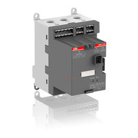
ABB UMC100.3 Manual (161 pages)
Univeral Motor Controller
Brand:
ABB
| Category:
Controller
| Size: 6.16 MB
Table of Contents
Important Notice
2
Table of Contents
3
How to Get Started
6
New Features in Comparison to Preceeding Versions
7
System Overview
8
Function Overview
8
Protection Functions
8
Communication
8
Metering, Monitoring and Diagnosis
9
Function Block Programming
9
Compatibility to Previous Versions of UMC100.3
9
Description of Components
10
Umc100.3
10
Building Blocks of UMC100.3
11
Dx111-Fbp.0
12
Dx122-Fbp.0
12
Vi150-Fbp.0
13
Vi155-Fbp.0
13
Ai111.0
14
Configuration Tool
15
LCD Panel
16
Installation
17
Assembly and Disassembly of UMC100.3 and IO Modules
17
Supplying the UMC and IO Modules
17
Connecting the IO Modules DX111-FBP.0 and DX122-FBP.0
17
Wiring Dx1Xx Inputs and Outputs
18
Connecting the Vi15X Voltage Module
19
Wiring Vi15X Inputs and Outputs
20
Connecting the AI111.0 Inputs
21
Connecting more than One Expansion Module
22
Connecting Contactors
22
Actual ABB Contactors - All Currents for 230 V AC (Extract):
22
Interfacing Contactors with Peak Current > 0,5 A: Types A50 and Larger
23
K2: Contactors with Peak Current >0.5 a
23
Motor Wiring
24
Connecting External Current Transformers (Cts)
25
Operation Details for Motors with Small Set Currents
26
Connecting the UMC100-PAN LCD Panel
27
Using the UMC100.3 in a PROFIBUS DP Network
28
PROFIBUS Line with UMC100.3 and PDP32
28
Integration with the GSD File
29
Integration with the Device Type Manager (DTM)
29
Using the UMC100.3 in a Devicenet Network
30
Using the UMC100.3 in a MODBUS RTU Network
31
Integration with the EDS File
31
Using the UMC100.3 in Withdrawable Applications
32
Commissioning Steps
33
Setting the Fieldbus Node Address
33
Configuration Via LCD Panel
34
Configuration from Within the Control System
34
Configuration Via Laptop
34
Test Position
35
Configuring the Motor Protection Functions
36
General Information
36
EOL and Current Based Protection Functions
36
Electronic Overload Protection
38
Block Diagram
38
Signal Flow of the Thermal Overload Protection
38
Example of Trip Class Selection
39
Example for the Trip Class Selection for a Given Motor
39
Cyclic Motor Operation Modes
40
Relevant Parameters
40
Long Start, Locked Rotor Protection
41
Signal Flow of the Locked Rotor Protection Function
41
Startup Phase of a Motor
41
High Current Protection
42
Signal Flow of the High Current Protection Function
42
Trend Diagram of the Motor Current over Time
42
Low Current Protection
43
Signal Flow of the Low Current Protection Function
43
Phase Loss Protection (Current)
44
Phase Imbalance Protection (Current)
44
Signalflow of the Phase Imbalance Function
44
Phase Sequence Protection
45
Earth Fault Protection
46
Signal Flow of the Earth Fault Protection Function
46
Protection Based on Internal Calculation
47
Signal Flow of the Internal Earth Fault Protection Function
47
Thermistor (PTC) Motor Protection Acc. to en 60947-8 (Type a Sensors)
48
Voltage and Power Protection Functions
49
Function Overview
50
Voltage Based Protection Functions
51
Signal Flow of the Voltage Based Protection and Monitoring Functions
51
Total Harmonic Distortion
51
Power Factor and Power Supervision
52
Voltage Dips, Load Shedding
54
The Load Shedding Logic Can be Triggered
54
Double Dips
57
RTD Based Temperature Supervision and Analog Inputs
58
Temperature Mode
58
Universal Mode
59
Configuring the Motor Management Functions
60
Starting and Stopping the Motor
60
Control Stations
60
Modes
60
How to Set the Mode
61
Activating Inching Mode
64
Emergency Start
65
Checkback Monitoring
65
Limit the Number of Starts
65
Using the Digital UMC Inputs
67
Using the Inputs DI3-DI5
67
Using the Multifunction Inputs DI0-DI2
67
Single Phase and Three Phase Operation Mode
69
Stand-Still Supervision
69
Run-Time Supervision
69
Control Functions
70
Control Function Transparent
70
Monitoring Data for Transparent
71
Command Data for Transparent
71
Control Function Overload Relay
72
Circuit Diagram of the UMC Overload Relay Mode
72
Monitoring Data for Overload Relay
73
Command Data Overload Relay
73
Control Function Direct Starter (DOL)
74
Timing Diagram for Direct Starter
75
Monitoring Data for Direct Starter
75
Command Data for Direct Starter
76
Control Function Reversing Starter (REV)
77
Timing Diagram for Changing Direction
78
Monitoring Data for Reversing Starter
79
Command Data for Reversing Starter
79
Control Function Star-Delta Starter
80
Monitoring Data for Star-Delta Starter
82
Command Data for Star-Delta Starter
82
Control Function Pole-Changing Starter
83
Monitoring Data for Pole-Changing Starter
85
Command Data for Pole-Changing Starter
85
Control Function Actuator
86
Open and Closed Position Via Limit Switches
87
Usage Without Torque Switches
87
Open and Closed Position Via Torque and Limit Switches
88
Command Data for Actuator
90
Control Function Softstarter
91
Monitoring Data for Softstarter
91
Command Data for Softstarter
92
Timing Diagram
92
Controlling Resistive Loads
94
Tripping Behavior
94
Restrictions for Power Calculation of Resistive Loads
94
Configuring the Communication Interfaces
95
Setting the Bus Address
95
Specific Communication Settings for Modbus RTU and Devicenet
95
Specific Communication Settings for Ethernet
95
Address Check When Using UMC in Motor Control Centres
96
Defining the Bus Fault Reaction
97
Ignore Block Parameters
97
Change I/O Data Length on the Fieldbus
97
Adjust Cyclically Transmitted Monitoring Words
98
Using Expansion Modules
99
Using a Digital IO Module (DX111-FBP.0/122-FBP.0)
99
Using a Voltage Module (VI150-FBP.0/155-FBP.0)
100
Using an Analog Input Module (AI111.0)
100
Activating a Voltage Module (VI150-FBP.0/155)-FBP.0
100
Using the Relay Output
100
The LCD Control Panel UMC100-PAN
101
Monitoring Status Information
102
The Menu Tree
102
Motor Management Parameters
104
Motor Protection Parameters
105
Communication Parameters
106
IO Module Parameters
106
Display Parameters
107
Maintenance and Service Parameters/Actions
107
Adjusting Parameters
108
Adjusting a Numerical Value
108
Selecting an Option from a List
108
Specifying a Text String
109
Use the LCD Panel as Parameter Storage
109
Use the LCD Panel as Automatic Parameter Backup Storage
110
The Function Stores
110
It Does Not Store
110
Activation of Auto Save Function
110
Acknowledge a Fault
112
Error Handling of the UMC
113
UMC100.3 Fault Indication
113
Fault Messages
113
Automatic Reset of Protection Faults
113
Resetting Parameters to Factory Defaults
118
Resetting the Password
118
Reading, Setting and Resetting Maintenance Counters
118
I/O-Module Status Codes
118
Replacing a UMC100.3
119
Replacing an I/O Module
119
Requesting Support
119
Check the Configuration
119
Parameters and Data Structures on a Fieldbus
120
Monitoring Data
120
Command Data
120
Diagnosis Data
121
Accessing Data on Ethernet/Ip
122
Accessing Data on PROFIBUS / PROFINET
122
Accessing Data on Modbus / Modbustcp
122
Accessing Data on Devicenet
122
Parameter Organisation
123
Protection Parameters
127
DX111-FBP.0 / DX122-FBP.0 Parameters
132
VI150-FBP.0 / VI155-FBP.0 Parameters
133
AI111.0 Parameters
135
UMC Display Parameters
136
Function Block Related Parameters
137
Aux Input Block
137
All Parameters Sorted by Parameter Number
138
Basic Circuit Diagrams
140
Direct Starter with IO Modules and 110-240V Supply
140
Emergency Stop Function for Direct Starter, Category 4
141
Emergency Stop Function for Reversing Starter, Category 4
142
Technical Data
143
Dimensions UMC100.3
156
Expansion Modules
157
Operating Panel
157
Operating Panel Protection Cap
157
Ethernet Communication Interfaces
158
Fieldbus Communication Interfaces
158
Advertisement
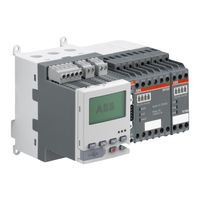
ABB UMC100.3 Manual (76 pages)
Custom Application Editor, Universal Motor Controller
Brand:
ABB
| Category:
Controller
| Size: 4.94 MB
Table of Contents
Important Notice
2
Table of Contents
3
How to Get Started
6
What Is New in this Version
7
Backward Compatibility
7
Consideration on Parameter I/O Data Profile
7
Introduction
8
Recommendations
8
The Editor
8
How to Proceed
9
Application Elements
10
Function Blocks
10
Connections and Lines
11
Parameter Values
12
Connectors
13
Left Open Pins
13
Comments
13
The Toolbar
14
Editing a Function Block Application
15
Inverting Inputs or Outputs
15
Creating the First Application
16
Sample Application
17
Edit Logic
19
Summary
22
Reusing Existing Solutions
23
Function Block Reference
25
Overview
25
UMC Output Function Blocks
31
Logic Functions
34
Basic Functions
43
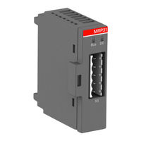
ABB UMC100.3 Manual (18 pages)
Modbus RTU communication module, Universal Motor Controller
Brand:
ABB
| Category:
Control Unit
| Size: 1.97 MB
Table of Contents
Table of Contents
3
Overview
4
Installation
5
Diagnosis
11
Technical Data
15
Dimensional Drawings
16
Ordering Data
17
Advertisement
ABB UMC100.3 Safety And Installation Instructions (2 pages)
Universal Motor Controller
Brand:
ABB
| Category:
Controller
| Size: 1.46 MB
Advertisement
Related Products
ABB UMC22-FBP
ABB UMC100-FBP
ABB UEMC 40 B Series
ABB UEMC 40 A Series
ABB UEMC 40 D Series
ABB UniSec
ABB UniSec DRC
ABB DODGE USN 308
ABB UNO-DM-3.3-TL-PLUS
ABB DODGE USN 626
ABB Categories
Industrial Equipment
Controller
Measuring Instruments
Battery Charger
DC Drives
More ABB Manuals
Login
Sign In
OR
Sign in with Facebook
Sign in with Google
Upload manual
Upload from disk
Upload from URL