Sign In
Upload
Manuals
Brands
Honeywell Manuals
Radar
BENDIX/KING RDR 2000
Honeywell BENDIX/KING RDR 2000 Manuals
Manuals and User Guides for Honeywell BENDIX/KING RDR 2000. We have
1
Honeywell BENDIX/KING RDR 2000 manual available for free PDF download: Installation Manual
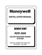
Honeywell BENDIX/KING RDR 2000 Installation Manual (128 pages)
COLOR WEATHER RADAR SYSTEM
Brand:
Honeywell
| Category:
Radar
| Size: 14.86 MB
Table of Contents
Table of Contents
3
General Information
19
Introduction
19
Equipment Description
19
Art 2000 Antenna/Receiver/Transmitter
20
In 182A Color Radar Indicator
20
Aa2010V/H and Aa2012V/Hantennas
21
CM 2000 Configuration Module
21
Technical Characteristics
21
Arinc 429 Information
21
1.3.2 Unit Information
22
Art 2000 Antenna/Receiver/Transmitter
23
In 182A Color Radar Indicator
25
Antennas
27
CM 2000 Configuration Module
27
Installation Kits
27
Accessories Required, but Not Supplied
29
Stabilization Requirements
29
Quadraxial Cable
29
14/28 VDC Converter
29
Radome
29
Configuration Module Programmer Kit
29
Optional Accessories
29
Installations with Efis
29
Gc 360A Radar Graphics Computer
30
Gc 362A Tcas Graphics Processor
30
Gc 381A Radar Graphics Computer
30
CC 2024 Checklist Unit
30
CC 2024B Checklist Controller
30
Iu 2023B Radar Graphics Computer
30
1.7 License Requirements
30
Installation
31
General
31
Unpacking and Inspecting Equipment
31
Equipment Installation
31
Cooling Considerations
31
Installation Planning
31
Art 2000 Dipswitch Settings
33
In 182A Color Radar Indicator Installation
36
Installation of Cables
36
Configuration Procedure Using Radar Indicator
37
Rdr Hidden
38
Rdr R-T Calibration Data Page
38
Efis Maint Functions
39
Configuration Procedure Using Efis
40
Subsystem Menu
40
R-T Calibration Data Page
40
Efis 40/50 Maintenance Menus Leading to Radar
42
Menus for Operation Configuration
43
Menus for Equipment Configuration
45
Diagnostics Menus for System Check
48
Gain Knob Calibration Function
53
Calibration Parameters in Azimuth Count Field
53
Tilt Knob Calibration Function
54
Pitch Gain
58
Pitch Offset
58
Roll Gain
59
Stabilization Calibration
60
Roll Offset
63
Menus for Stabilization Calibration
64
Ref Gain Adjust
64
Ahrs Pitch Offset
67
Ahrs Roll Offset
67
Pre-Flight Test Procedures
68
Rf Operation Check
68
Save Configuration
68
Interference Check
69
Preflight Check
69
Flight Test Procedures
70
Stabilization Check
70
Vertical Profile Check
71
Crimp Tools
75
Art 2000 Pinout Diagram
76
In 182A Pinout Diagram
78
Configuration Module Pinout Diagram
80
Art 2000 Outline and Mounting Drawing (Horizontally Polarized Antenna)
81
Art 2000 Outline and Mounting Drawing (Vertically Polarized Antenna)
82
Aircraft Power and Ground Interconnect
89
Configuration Module Interconnect
90
Single Rds Indicator Interconnect
91
Art Interface
93
Analog Stabilization Interconnect
94
Ahrs Stabilization Interconnect
98
Efis 40/50 Interconnect
99
Efis 40/50 Interconnect
100
Rs 181A/811A to Art 2000 Harness Connector
105
Controls and Display
107
In182A Controls and Display
107
In 182A Control Functions
109
Art 2000 Fault Codes
110
In 182A Function Selector Switch Positions
110
Operating Procedures
111
Pushbutton Types
111
Typical Test Pattern Display
113
Typical Weather Display
114
Advertisement
Advertisement
Related Products
Honeywell IntuVue RDR-7000
Honeywell SMARTLINE RM77
Honeywell IntuVue RDR-4000
Honeywell RDWL313A2000
Honeywell RDWL311A2000
Honeywell RDWL313P2000
Honeywell RDWL515P2000
Honeywell RDWL515A2000
Honeywell RDWL917AX2000
Honeywell RDWL515A2000/U
Honeywell Categories
Thermostat
Controller
Control Unit
Security Camera
Accessories
More Honeywell Manuals
Login
Sign In
OR
Sign in with Facebook
Sign in with Google
Upload manual
Upload from disk
Upload from URL