Sign In
Upload
Manuals
Brands
Honeywell Manuals
Control Unit
KT73
Honeywell KT73 Manuals
Manuals and User Guides for Honeywell KT73. We have
2
Honeywell KT73 manuals available for free PDF download: Installation Manual, Theory Of Operation
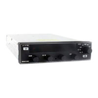
Honeywell KT73 Installation Manual (95 pages)
MODE S TRANSPONDER
Brand:
Honeywell
| Category:
Marine Radio
| Size: 2.1 MB
Table of Contents
Table of Contents
5
Paragraph
9
Introduction
9
Equipment Description
9
General Description
9
General Information
9
Hardware
9
Features
10
Kt 73 Technical Characteristics
11
Bandwidth
12
Kt 73 Receiver Characteristics
12
Sensitivity and Dynamic Range
12
Sensitivity Variation with Frequency
12
Antenna
13
ATCRBS Reply Rate Capability
13
Mode S Reply Rate Capability
13
RF Peak Power Output
13
Unwanted Output Power
13
Configurations Available
14
Kt 73 Installation Kit
14
Units and Accessories Supplied
14
Accessories Required, but Not Supplied
15
Licensing Requirements
16
Instructions for Continued Airworthiness
16
Paragraph
17
General Information
17
Unpacking and Inspecting Equipment
17
Avionics Cooling Requirements for Panel Mounted Equipment
18
Kt 73 Interconnection and Cable Harness Fabrication
18
Functional Pinout Descriptions
19
Primary Power and Circuit Breaker Requirements and Wiring
19
Main Connector - JKT73-1
20
Auxiliary Connector - JKT73-2
21
Antenna Connector - JKT73-3
22
External Connector - JKT73-4
22
Antenna
23
Equipment Location
23
Transponder and Mounting Tray Locations
23
Aircraft Address Programming Options
24
Kt 73 Installation
24
New Transponder Tray Installations
24
Retrofit into Existing KT 70, KT 71, and KT 76C Installations
24
Molex Connector Assembly Procedure
25
Solderless Contact Terminal Assembly Using Pliers
25
Contact Insertion into Molex Connector Housing
26
Extraction of Contact from Molex Connector
26
Positronic Connector Assembly Procedure
26
Crimping Tools
27
Crimping Pressure Adjustment
29
Contact Extraction Tool
31
Contact Insertion Tool
31
Cycle-Controlled Step Adjustable Hand Crimp Tool
31
Crimp Wire to Contact
32
Cross Section of Correctly Crimped Contact
33
Examples of Crimping Faults
33
Inspect Crimp
33
Main Connector - JKT73-1 Front View
35
Auxiliary Connector - JKT73-2 Front View
36
External Connector - JKT73-4 Front View
37
Kt 73 Installation Drawing
39
Single Kt 73 Basic Interconnection Drawing
41
Single Kt 73 with Tis Interconnection Drawing
43
Single Kt 73 with Adlp or Ads-B Interconnection Drawing
45
Single Kt 73 with Serial Altitude Inputs Interconnection Drawing
47
Dual Kt 73 Basic Interconnection Drawing
49
Dual Kt 73 with Serial Altitude Inputs Interconnection Drawing
53
Rf Connector Drawing
59
Acceptable Cable Connections Drawing
61
Cable Connector Drawing
63
Type “N” and “C” Connector Assembly Drawing
64
Bnc Connector Assembly Drawing
65
Inspection/Check Procedure
67
Post-Installation Checkout/Operation
67
System Interwiring Check
67
Transponder System Checkout
67
Post-Installation Test
68
Pretest Setup
68
Visual Inspection
68
Aircraft Address and Maximum Airspeed Verification
69
Conformity Inspection
69
Ramp Test
69
Ramp Test (TIS And/Or ADS-B Functions)
71
Kt 73 Front Panel
73
Operation
73
Programming Mode
73
Kt 73 Configuration Menu
75
A/C Addr
77
Programmable Parameters
77
Alt Src
78
Kt 73 Lower and Upper Maximum Airspeed
78
Max Air
78
Air Vol
79
Auto Gnd
79
ENH FUNC (429 or 232 Selected)
79
ENH FUNC (Gillham Selected)
79
Adsb Emt
80
Gnd Vol
80
Detailed Operating Modes
81
Functional Modes
81
Off
81
Kt 73 Ground Mode
82
Kt 73 Standby Mode
82
Kt 73 on Mode
83
Kt 73 Altitude Mode
84
Kt 73 Flight ID Mode
85
Kt 73 Test Mode
85
When the Unit Is in TST (Test) Mode
86
Front Panel Operation
87
Ground Mode
87
Idt (Ident)
87
On/Altitude Mode
87
Altitude Display
88
Last Code Reversion
88
Vfr Operation
88
VFR Programming
88
Built in Test Equipment (Bite)
89
Display Brightness Adjustment
89
Gas Discharge Display
89
Internal Eeprom and Remote Configuration Module
89
Environmental Qualification Forms
91
Equipment Installation
17
General
17
Figure
82
Advertisement
Honeywell KT73 Theory Of Operation (4 pages)
Transmitter/Modulator Module
Brand:
Honeywell
| Category:
Control Unit
| Size: 0.1 MB
Table of Contents
1.0 Modulator Board
1
1.1 TX_SENSE Module
1
1.2 50 V Regulator
1
1.3 Collector Modulator
2
1.4 Emitter Modulator
2
2.0 Transmitter Board
3
2.1 Power Oscillator
3
2.2 Bandpass Filter FL1
3
2.3 the 6 Db Coupler, W1
4
2.4 the Zero Db Attenuator
4
2.5 Power Amplifier
4
2.6 TX/RX Switch
4
2.7 the Low Pass Filter
4
Advertisement
Related Products
Honeywell BENDIX/KING KDF 806
Honeywell BENDIX/KING KFS 586A
Honeywell IDENT KEY 3
Honeywell Kromschroder GIK 20R
Honeywell Kromschroder GIK 40R
Honeywell Kromschroder GIK 50N
Honeywell Kromschroder GIK 65A
Honeywell Kromschroder GIK 80A
Honeywell Kromschroder GIK 100A
Honeywell Kromschroder GIK 150F
Honeywell Categories
Thermostat
Controller
Control Unit
Security Camera
Accessories
More Honeywell Manuals
Login
Sign In
OR
Sign in with Facebook
Sign in with Google
Upload manual
Upload from disk
Upload from URL