Sign In
Upload
Manuals
Brands
HP Manuals
Test Equipment
37717C
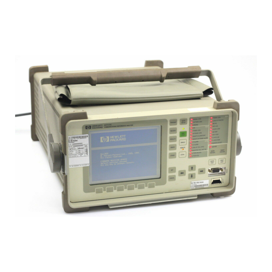
HP 37717C Manuals
Manuals and User Guides for HP 37717C. We have
4
HP 37717C manuals available for free PDF download: Calibration Manual, User Manual, Operating Manual, Configuration Manual
HP 37717C Calibration Manual (399 pages)
Communications Performance Analyzer
Brand:
HP
| Category:
Test Equipment
| Size: 2.68 MB
Table of Contents
Table of Contents
6
General Information Warranty
22
Responsibilities of the Customer
23
Certification
24
Assistance
24
Notice
24
Restricted Rights Legend
24
Instruments Covered by Manual
25
Storage and Shipment
25
Repackaging for Shipment
25
Weight and Dimensions
26
Safety Precautions for the Operator
27
Lifting/Carrying the HP 37717C
27
Using both Arms to Lift Instrument
27
Safety Symbols
28
Operators Maintenance
29
Cleaning
29
Cabinet Cleaning
29
Optical Connector Cleaning
29
Power Supply Fuse Replacement
30
Statement of Compliance
31
Australian EMC Regulations
31
Noise Declaration (German)
31
Electromagnetic Compatibility
32
Electrostatic Discharge
32
Declaration of Conformity
33
Specifications
34
Unframed PDH (Option UKK)
34
Structured PDH (Options UKJ, UKL)
35
DS1/DS3/E1/E3 Structured Test Interfaces (Option 110)
38
Dsn/Pdh Receiver
39
SDH MODULE: Option US1
40
STS-3/STM-1E and STM-0/STM-1E Test and Interfacing (Option 120) (for SDH Specification See A3R)
47
STM-1/STM-4 OPTICAL INTERFACE: Option UH2
55
STM-1/STM-4 OPTICAL INTERFACE: Option URU
55
Ukt
56
STM-1/STM-4 OPTICAL INTERFACE (1310 Nm) with STM-4 Overhead Option UKT
56
STM-1/STM-4 (1310/1550 Nm) OPTICAL INTERFACE with STM-4 Overhead Option USN
57
STM-0/STM-1/STM-4 OPTICAL INTERFACE (1310 Nm) with STM-4C Overhead Option 131
59
Overhead Option 130
61
STM-0/STM-1/STM-4 OPTICAL INTERFACE (1310/1550 Nm) with STM-4C Overhead Option 130
61
SDH Binary Interface (Option 0YH)
63
MEASUREMENTS and ANALYSIS
75
UNFRAMED PDH (Option UKK)
76
SDH (Option US1)
78
JITTER (Options UHN, A1M, A1N, A1P, A3L, A3V and A3N)
83
ATM Measurement (Option UKN)
83
Recommended Test Equipment
88
Installation
90
Initial Inspection
90
Operating Environment
91
Preparation for Use
92
Power Requirements
92
Fuses
92
Fuse Replacement
92
Connecting to the Power Supply
93
Line Voltage Selector Switch
93
Power Cord
94
Connecting to the Network
95
All Connectors
95
Electrical Interface Connectors
95
Optical Interface Connectors
99
Laser Product Classification
99
Laser Warning Symbols
100
Swedish and Finnish Labels
101
Location of Laser Apertures on Options 130 and 131
102
Cleaning Optical Connectors
103
Connecting Accessories
104
Base-T Lan Connection Radiated Emissions
104
Hewlett-Packard Interface Bus
105
HP-IB Address Selection
106
Additional Precautions for Service Engineers
107
Safety Precautions
107
ESD Precautions
107
Performance Tests
110
Introduction
110
Equipment Required
110
Extra Modules Required
110
Performance Test Record
110
Calibration Cycle
110
Recall Default Settings
111
Self Test - All Options
112
Description
112
Additional Tests
113
PDH Internal Transmitter Clocks (Options UKK, [USB], UKJ, [USA])
115
Specifications
115
Description
115
Equipment Required
115
Procedure
116
Frequency Offsets
117
PDH Transmitter Output
118
Specifications
118
Description
119
Equipment Required
119
Procedure
119
Kb/S Balanced Output
120
Mb/S Balanced Output
123
Mb/S Unbalanced Output
123
Multiple PDH Transmitter Outputs (Options UHC, [US6])
131
Specifications
131
Description
131
Equipment Required
132
Procedure
132
Kb/S Output Pulse
132
Kb/S Additional Outputs Delay
133
Mb/S Output Pulse
134
Mb/S Additional Output Delay
136
Mb/S Output Pulse
136
Mb/S Additional Output Delay
138
Mb/S Output Pulse
138
Mb/S Additional Outputs Delay
140
Mb/S Output Pulse
140
Additional Outputs Delay at 139.264 Mb/S
143
PDH Frame Analysis (Options UKK, [USB])
144
Specifications
144
Equipment Required
144
Description
144
Procedure
145
Option UKK, [USB] Unstructured PDH
145
Option UKJ, [USA] Structured PDH
145
Mb/S Frame Analysis
146
Mb/S Frame Analysis
148
Mb/S Frame Analysis
149
Mb/S Frame Analysis
150
PDH Receiver Equalization (Options UKK, [USB], UKJ, [USA], UKL, [USC], UKN, [USE])
152
Specifications
152
Description
152
Equipment Required
152
Procedure
153
Kb/S
153
Mb/S
154
Mb/S
155
PDH Receiver Monitor Levels (Options UKK, [USB])
156
Specification
156
Description
156
Equipment Required
156
Procedure
156
Kb/S
157
Mb/S
158
SPDH Receiver Monitor Levels (Options UKJ, [USA], UKL, [USC], UKN, [USE])
159
Specifications
159
Description
159
Equipment Required
159
Procedure
160
Mb/S
161
Mb/S
162
Mb/S
163
External 2Mb/S Mux/Demux (Options UKJ, [USA], UKN, [USA])
164
Specifications
164
Equipment Required
165
Procedure
165
External 2Mb/S Demux (Options UKL, [USC])
171
Specifications
171
Description
171
Equipment Required
171
Procedure
172
PDH Receiver Monitor Levels (Special Option 808)
177
Specification
177
Description
177
Procedure
177
Kb/S
178
Mb/S
179
PDH Error Output (Options UKK, [USB])
180
Specifications
180
Description
180
Equipment Required
180
Procedure
180
Error Output Signal
181
PDH Frequency Measurement and Looped Clock (Options UKK, [USB], UKJ, [USA], UKL, [USC], UKN, [USE])
182
Specifications
182
Description
182
Equipment Required
182
Procedure
182
Internal SDH Transmitter Clock (Options US1, [US5], A1T, [A1U], A3R [A3S])
186
Specification
186
Description
186
Equipment Required
186
Procedure
186
SDH Frequency Offsets (Options US1, [US5], A1T, [A1U], A3R [A3S], 120)
188
Specifications
188
Description
188
Equipment Required
188
Procedure
188
External MTS Clock (Options US1, [US5], A1T, [A1U], A3R [A3S], 120)
191
Specifications
191
Description
191
Procedure
191
External MTS - 2Mhz Clock
191
External MTS - 2Mhz Data
192
BITS 1.5 Mb/S (Option 120 Only)
192
External - MTS 64K Clock
193
Stm-1 Rx
193
Transmitter Output Waveshape (Options US1, [US5], A1T, [A1U], A3R [A3S], 120)
194
Specifications
194
Description
194
Procedure
194
Receiver Monitor Input (Options US1, [US5])
200
Specification
200
Description
200
Procedure
200
Receiver Monitor Input (Options A1T, [A1U], A3R [A3S], 120)
202
Specification
202
Description
202
Equipment Required
202
Procedure
202
Receiver Monitor Input (Special Option 808)
204
Specification
204
Description
204
Equipment Required
204
Procedure
204
Receiver Input Equalization (Options US1, [US5], A1T, [A1U], A3R [A3S], 120)
206
Specification
206
Description
206
Procedure
206
Optical Interface (Option UH1)
207
Specification (Transmitter)
207
Specification (Receiver)
207
Description
207
Equipment Required
208
Procedure
208
STM-1/STM-4 Optical Interface (Option UH2)
210
Specification (Transmitter)
210
Specification (Receiver)
210
Description
210
Equipment Required
211
Procedure
211
STM-1/STM-4, 1550Nm Optical Interface (Option URU)
213
Specification (Transmitter)
213
Specification (Receiver)
213
Description
213
Equipment Required
214
Procedure
214
STM-1/STM-4 Optical Interface (Options UKT, USN)
218
Specification (Transmitter)
218
Specification (Receiver)
218
Description
218
Equipment Required
219
Procedure Option UKT and USN
220
Procedure Option USN Only
222
STM-1/STM-4 Optical Interface (Options 130, 131)
226
Specification (Transmitter)
226
Specification (Receiver)
226
Description
226
Procedure Option 130 and 131
227
Procedure Option 130 Only
230
Transmitted Jitter Amplitude Accuracy (Option UHK)
234
Specifications
234
Description
235
Equipment Required
235
Pre-Adjustment Setup
235
Procedure
236
Transmitted Jitter/Wander Amplitude Accuracy (Option A3K [A3Q])
241
Specifications
241
Jitter Generation
241
Amplitude Range
241
External Jitter
242
Wander Generation
242
Wander Timing Reference Input
242
External Jitter Modulation Input
242
Description
243
Equipment Required
244
Pre-Adjustment Setup
244
Procedure
245
Transmitted PDH Jitter Amplitude Accuracy on Range 1
245
Transmitted PDH Jitter Accuracy on Range 10
248
Transmitted SDH Jitter Accuracy on Ranges 1 & 10
250
Transmitted SDH Jitter Accuracy on Range 50
252
Transmitted PDH Jitter Accuracy on Range 80
253
External Jitter Generation
254
Wander Generation
255
Received Jitter Accuracy (Options UHN, [US9], A1M [A1Q], A1N [A1R], A1P [A1S], A3L [A3M], A3V [A3W], A3N [A3P])
258
Specifications
258
Description
258
Equipment Required
258
Received Jitter Accuracy Procedure
259
Hit Count
260
Demodulated Jitter Output
261
Wander/Slips Measurement (Options UHN, [US9], A1M [A1Q], A1N [A1R], A1P [A1S], A3L [A3M], A3V [A3W], A3N [A3P])
262
Specifications
262
Timing Reference Input
262
Wander Measurement
262
Description
263
Equipment Required
263
Procedure
263
Jitter Receiver STM-1E Input Equalization (Options A1M [A1Q], A1N [A1R], A1P [A1S], A3L [A3M], A3V [A3W], A3N [A3P])
268
Specification
268
Description
268
Equipment Required
268
Procedure
268
Jitter Receiver STM-1E Monitor Input (Options A1M [A1Q], A1N [A1R], A1P [A1S], A3L [A3M], A3V [A3W], A3N [A3P])
269
Specification
269
Description
269
Equipment Required
269
Procedure
269
Jitter Receiver STM-1 Optical Interface (Options A1N, [A1R], A3V [A3W])
271
Specification
271
Description
271
Equipment Required
271
Procedure
272
Jitter Receiver STM-1/STM-4 Optical Interface (Options A1P, [A1S], A3N [A3P])
274
Specification
274
Description
274
Equipment Required
274
Procedure
275
PDH Binary Interfaces (Option UH3, [US7])
277
Specifications
277
Description
278
Procedure
278
External Clock Thresholds
278
External Clock Mark to Space Ratio
281
ETSI/ANSI Internal Transmitter Clock Rates (Option UKZ)
285
Specification
285
Description
285
DS3 Frequency Accuracy
285
E1 (2.048Mb/S) Frequency Accuracy
286
E3 (34.368Mb/S) Frequency Accuracy
286
DS1 Frequency Accuracy
287
ETSI/ANSI Transmitter Output Level and Waveshape (Option UKZ)
288
Specifications
288
Description
288
Mb/S Positive Pulse
289
Mb/S Negative Pulse
290
Mb/S Positive Pulse
291
Mb/S Negative Pulse
293
Positive Pulse
294
DSX-3 Positive Pulse
294
Negative Pulse
295
DSX-3 Negative Pulse
295
Positive Pulse
296
DSX-1 Positive Pulse
296
Negative Pulse
297
DSX-1 Negative Pulse
297
ETSI/ANSI Receiver Equalization (Option UKZ)
299
Specifications
299
Description
299
Mb/S Equalization
299
Mb/S Equalization
300
DS3 Equalization
301
DS1 Equalization
302
ETSI/ANSI Receiver Monitor Levels (Option UKZ)
303
Specifications
303
Description
303
Mb/S 20Db Monitor
304
Mb/S 26Db Monitor
305
Mb/S 30Db Monitor
305
Mb/S 20Db Monitor
305
Mb/S 26Db Monitor
306
DS3 20Db Monitor
307
DS3 26Db Monitor
307
DS1 20Db Monitor
308
DS1 26Db Monitor
309
DS1 30Db Monitor
309
Trigger Output (Option UKZ)
310
Specification
310
Description
310
Trigger Pulse
310
Internal SONET Transmitter Clock (Option 120)
313
Specification
313
Description
313
Equipment Required
313
Procedure
313
SONET Frequency Offsets (Option 120)
315
Specifications
315
Description
315
Equipment Required
315
Procedure
315
Transmitter Output Waveshape (Option 120)
318
Specifications
318
Description
318
Procedure
318
STM-1/STS-3 Receiver Monitor Input (Options A1T, A1U, A3R, [A3S], 120)
324
Specification
324
Description
324
Equipment Required
324
Procedure
324
STM-1/STS-3 Receiver Input Equalization (Options US1, [US5], A1T, [A1U], A3R, [A3S],120)
326
Specification
326
Description
326
Procedure
326
ETSI/ANSI Internal Transmitter Clock Rates (Option 110)
327
Specification
327
Description
327
E3 (34.368Mb/S) Frequency Accuracy
327
E1 (2.048Mb/S) Frequency Accuracy
328
DS1 Frequency Accuracy
328
DS3 Frequency Accuracy
328
ETSI/ANSI Transmitter Output Level and Waveshape (Option 110)
330
Specification
330
Description
330
Mb/S Positive Pulse
331
Mb/S Negative Pulse
332
Mb/S Positive Pulse
332
Mb/S Negative Pulse
334
Positive Pulse
334
Negative Pulse
335
Positive Pulse
336
Negative Pulse
337
ETSI/ANSI Receiver Equalization (Option 110)
338
Specifications
338
Description
338
Mb/S Equalization
338
Mb/S Equalization
339
DS3 Equalization
340
DS1 Equalization
341
ETSI/ANSI Receiver Monitor Levels (Option 110)
342
Specifications
342
Description
342
Equipment Required
342
Procedure
343
Mb/S
344
Mb/S (DS-1)
345
Mb/S
345
Mb/S (DS-3)
345
Performance Test Record
346
1 Terms
376
ETSI / ANSI Equivalent Terms
376
Current / Previous Terminology
378
Testing
388
Jitter Transmitter Module Calibration
389
Description
389
Equipment
389
Pre-Adjustment Setup
389
Jitter Transmitter Calibration Procedure
390
Advertisement
HP
37717C
User Manual
HP 37717C User Manual (200 pages)
Communications Performance Analyzer
Brand:
HP
| Category:
Measuring Instruments
| Size: 1.44 MB
Table of Contents
Table of Contents
6
1 Setting the Interfaces
12
Setting PDH Transmit Interface
13
Setting PDH Transmit Binary Interface
15
Setting SONET Transmit Interface
17
Setting Jitter Transmit Interface
20
Setting Wander Transmit Interface
21
Selecting the Physical Transmit Interface for ATM Payloads
23
Setting SONET THRU Mode
25
Using Autosetup
27
Setting PDH Receive Interface
29
Setting PDH Receive Binary Interface
31
Setting SONET Receive Interface
32
Setting Jitter Receive Interface
34
Selecting the Physical Receive Interface for ATM Payloads
36
2 Selecting Test Features
38
Using Transmit Overhead Setup
39
Using Receive Overhead Monitor
41
Setting Overhead Trace Messages
43
Generating Overhead Sequences
44
Using Receive Overhead Capture
46
Adding Frequency Offset to SONET Signal
48
Adding Frequency Offset to the PDH Signal
50
Setting up Signaling Bits
51
Setting Transmit Structured Payload/Test Signal (Options UKJ or 110)
54
Setting Transmit Structured Payload/Test Signal (Options UKJ or
55
Setting Receive Structured Payload/Test Signal
56
Connecting a Telephone Handset
58
Setting Transmit N X 64 Kb/S (N X 56 Kb/S) Structured Payload/Test Signal
59
Setting Receive N X 64 Kb/S (N X 56 Kb/S) Structured Payload/Test Signal
61
Inserting an External PDH Payload/Test Signal
63
Dropping an External Payload/Test Signal
65
Selecting ATM Cell Stream Payload
67
Selecting ATM Cell Stream Timing Distribution
68
Selecting ATM Cell Stream Headers and Interface
69
Adding Errors & Alarms at the SONET Interface
70
Adding Errors & Alarms to the PDH Interface/Pdh Payload
71
Using FEAC Codes in the HP 37717C
73
Adding ATM Errors and Alarms
76
Setting PDH Spare Bits
77
Adding Pointer Adjustments
78
T1.105/GR-253 Pointer Sequences Explained
80
Using Pointer Graph Test Function
86
Stressing Optical Clock Recovery Circuits
88
Generating Automatic Protection Switch Messages
89
Inserting & Dropping Data Communications Channel
90
3 Making Measurements
92
Using Overhead BER Test Function
93
Test Timing
94
Making SONET Analysis Measurements
95
Making PDH Analysis Measurements
96
Measuring Jitter
98
Measuring Wander
100
Measuring Frequency
102
Measuring Optical Power
103
Measuring Round Trip Delay
104
Monitoring Signaling Bits
106
Measuring Service Disruption Time
108
Performing an SONET Tributary Scan
110
Performing a SONET Alarm Scan
112
Performing a PDH Alarm Scan
114
Selecting the ATM Measurement Parameters
115
Making ATM Measurements
117
Measuring Cell Transfer Delay and Cell Delay Variation
118
Measuring ATM Non-Conforming Cells and One-Point Cell Delay Variation
120
Monitoring ATM Alarms
121
4 Storing, Logging and Printing
122
Saving Graphics Results to Instrument Store
123
Recalling Stored Graph Results
124
Viewing the Bar Graph Display
126
Viewing the Graphics Error and Alarm Summaries
128
Logging Graph Displays
130
Logging Results
131
Logging Results to Parallel (Centronics) Printer
134
Logging Results to HP-IB Printer
135
Logging Results to Internal Printer
136
Logging Results to RS-232-C Printer
137
Printing Results from Disk
138
Connecting an HP Deskjet Printer to a Parallel Port
139
Changing Internal Printer Paper
140
Cleaning Internal Printer Print Head
143
5 Using Instrument and Disk Storage
144
Storing Configurations in Instrument Store
145
Storing Current Configurations on Disk
146
Setting up a Title for Configurations in Instrument Store
147
Recalling Configurations from Instrument Store
148
Formatting a Disk
149
Labeling a Disk
150
Managing Files and Directories on Disk
151
Adding Descriptors to Disk Files
155
Saving Graphics Results to Disk
156
Saving Data Logging to Disk
158
Recalling Configuration from Disk
159
Recalling Graphics Results from Disk
160
Copying Configuration from Instrument Store to Disk
161
Copying Configuration from Disk to Instrument Store
162
Copying Graphics Results from Instrument Store to Disk
163
Deleting a File on Disk
165
Deleting a Directory on Disk
166
Renaming a File on Disk
167
Creating a Directory on Disk
168
6 Selecting and Using "Other" Features
170
Coupling Transmit and Receive Settings
171
Suspending Test on Signal Loss
172
Setting Time & Date
173
Enabling Keyboard Lock
174
Enabling Beep on Received Error
175
Enabling Analysis Control
176
Setting Error Threshold Indication
177
Dumping Display to Disk
178
Setting Screen Brightness and Color
180
Running Self Test
181
7 SPE Background Patterns
186
8 ETSI/ANSI Terminology
188
ETSI/ANSI Conversion and Equivalent Terms
189
HP 37717C Operating Manual (80 pages)
Communications Performance Analyzer, PDH / DSn
Brand:
HP
| Category:
Measuring Instruments
| Size: 0.67 MB
Table of Contents
Table of Contents
5
HP 37717C PDH / Dsn Features
7
Introduction to PDH / Dsn
8
Options with PDH / Dsn Capability
9
Unstructured PDH Generation and Measurement. Option UKK (USB)
9
Structured PDH Generation and Measurement. Options UKJ (USA) and UKN (USE)
10
DS1, DS3, E1 and E3 Transmit and Receive Interfaces for ATM Payloads. Option UKZ
11
E1, E3 and E4 Transmit and Receive Interfaces for ATM Payloads. Option UKN (USE)
12
Binary Interfaces. Option UH3 (US7)
13
Multiple PDH Outputs. Option UHC (US6)
14
PDH / Dsn Display Reference
15
Unstructured PDH Generation and Measurement. Option UKK (USB)
15
Structured PDH Generation and Measurement. Options UKJ (USA) or UKN (USE)
17
Option UKZ
21
DS1, DS3, E1 and E3 Transmit and Receive Interfaces for ATM Payloads. Option UKZ
21
E1, E3 and E4 Transmit and Receive Interfaces for ATM Payloads. Option UKN (USE)
25
Binary Interfaces. Option UH3 (US7)
28
PDH / Dsn Testing with the HP 37717C
31
Alarm Monitoring
32
Analysis of N X 64 Kb/S
35
BERT Testing
39
Cross Multiplexer Testing
44
FAS Monitoring
50
Frequency Measurement
54
Frequency Offset Tolerance
57
Multiplexer Testing
61
Round Trip Delay
66
M2100, M2110, M2120 Analysis
69
Monitoring DS3 with ATM Payloads
73
Advertisement
HP 37717C Configuration Manual (12 pages)
Hewlett-Packard Communications Performance Analyzer Configuration Guide
Brand:
HP
| Category:
Test Equipment
| Size: 0.32 MB
Table of Contents
Configuration Guide
1
Table of Contents
2
Introduction
3
Example Configurations
4
Configuring the HP 37717C Communications Performance Analyzer
5
Module Interworking
6
Other Options and Accessories
12
Advertisement
Related Products
HP 377707-002
HP COMPAQ 377703-001
HP 37718A OmniBER 718
HP 37719A
HP Agilent 37717B PDH
HP Agilent 37717B SDH
HP 370697-002
HP PHOTOSMART 370
HP 376227-B21 - ProLiant InfiniBand 4x Fabric Copper Switch
HP 3700 - Color LaserJet Laser Printer
HP Categories
Desktop
Laptop
Server
Monitor
Switch
More HP Manuals
Login
Sign In
OR
Sign in with Facebook
Sign in with Google
Upload manual
Upload from disk
Upload from URL