Sign In
Upload
Manuals
Brands
HP Manuals
Power Supply
6012A
HP 6012A Manuals
Manuals and User Guides for HP 6012A. We have
1
HP 6012A manual available for free PDF download: Operating And Service Manual
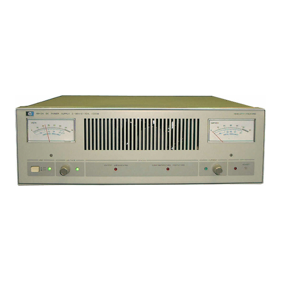
HP 6012A Operating And Service Manual (98 pages)
Autoranging DC Power Supply
Brand:
HP
| Category:
Power Supply
| Size: 5.92 MB
Table of Contents
Safety Information
2
Table of Contents
3
Description
5
Instrument and Manual Identification
5
Options
5
Accessories
6
Specifications
6
Meters and Indicators
8
Multiple Unit Operation
8
Temperature Ratings
8
Backpressure
8
Installation
9
Initial Inspection
9
Repackaging for Shipment
9
Location and Cooling
9
Input Power Requirements
10
Power Connection
10
Power Cord Preparation
10
AC Line Impedance Check
11
Line Voltage Option Conversion
11
Rack Mounting
11
Operating Instructions
13
Turn-On Checkout Procedure
13
Connecting the Load
13
Front Panel Controls and Indicators
13
Copper Wire Current-Carrying Capacity
14
Connecting a Bypass Capacitor
14
Protective Circuits
15
Operating Modes
15
Normal Operating Mode
15
Normal Strapping
15
Constant Voltage Operation
16
Constant Current Operation
16
Overvoltage Protection (OVP)
16
Overrange
16
Remote Voltage Sensing
17
Remote Programming
17
Resistance Programming of Output Voltage
18
Voltage Programming of Output Voltage
19
Scaled Voltage Programming of Output Voltage
19
Current Programming of Output Voltage
19
Resistance Programming of Output Current
20
Voltage Programming of Output Current
20
Auto-Parallel Operation
21
Scaled Voltage Programming of Output Current
21
Current Programming of Output Current
21
Auto-Series Operation
22
Setting the Voltage and Current Controls
22
Overvoltage Protection in Auto-Parallel
22
Auto-Parallel with Remote Sensing
22
Resistor Values
23
Auto-Tracking Operation
24
Overvoltage Protection in Auto-Series
24
Auto-Series with Remote Sensing
24
Setting the Current Controls
25
Auto-Tracking with Remote Programming
25
I-Monitor Output Signal
26
Principles of Operation
27
Autoranging Power Supply Vs. Conventional Power Supply
27
Simplified Schematic Description
27
Input AC Circuits
27
Simplified Schematic
28
Constant Voltage (CV) Circuit
29
Constatr Circuit (CC) Circuit
29
Control Voltage
30
Pulse Width Modulator (PWM)
30
PWM Fast Turn off
30
FET Control Signals Timing Diagram
30
Primary Current (Ip) Limit
31
Down Programmer
31
Overvoltage Protection Circuit (OVP)
31
Bias Voltage Detector
31
Maintenance
32
Test Equipment Required
32
Performance Test
33
Measurement Techniques
33
Constant Voltage Tests
33
Select a Load
33
Load Effect (Load Regulation)
34
Source Effect (Line Regulation)
34
PARD (Ripple and Noise)
34
Ripple Measurement Techniques
34
Ripple Measurement Procedure
35
Noise Spike Measurement
35
Load Transient Recovery Time
35
Temperature Coefficient
36
Drift (Stability)
36
Constant-Current Tests
37
Current Output and Ammeter Accuracy
37
Troubleshooting
38
Overall Troubleshooting Tree
39
Troubleshooting Bias Supplies
40
Overall Trouble Isolation
41
Slow Start Setup
41
Bias Voltage Check
41
Slow Start Procedure
42
Relay Driver
43
Clock and PWM
43
FET Assemblies
43
CV Circuit
43
Repair and Replacement
44
Outside Cover Removal
44
CC Circuit
44
OVP Circuit
44
A2 Control Board Removal
45
A3 FET Boards and A4 Output Diode Board Removal
45
FET Board Disassembly
45
Output Diode Board Disassembly
46
A1 Main Board Removal
46
Relay K1 Removal
47
Component Access through Bottom Chassis
47
Front Panel Removal
47
Adjustment and Calibration
48
Meter Zero Adjustment
48
Ip Limit Adjustment
49
Constant Voltage Offset Adjustment
49
Constant-Current-Source Adjustment
49
Ammeter Adjustment/Voltmeter Adjustment
49
Replaceable Parts
50
Component Location Illustrations and Circuit Diagrams
59
System Option 002
67
System Option 002 Installation and Operation
69
Connector Assembly Procedure
69
Resistance Control
70
Voltage Control
70
Current Control
70
Resistance Programming of Output Voltage And/Or Current
71
Remote Monitoring
73
Calculating Value of Series Dropping Resistor
73
Status Indicators
74
Remote Control
74
Remote Reset
74
Power-On Preset
75
Multiple Supply System Shutdown
75
Remote/Local Programming
76
Bias Supplies
76
Option Board Maintenance
77
Removal of the Option Board
77
Troubleshooting Resistance and Voltage Programming
77
Troubleshooting Current Programming
77
Troubleshooting Status Indicators
78
Bias Supply Adjustments
79
Troubleshooting Remote Shutdown
79
+15 V Supply Adjustment
79
-15 V Supply Adjustment
79
Logic Symbols and Definitions
83
Indicator and Qualifier Symbols
83
Option 002 Board Component Location
84
Option 002 Schematic Diagram
88
100 Vac Input Power Option 100
89
Advertisement
Advertisement
Related Products
HP 6034A
HP 6033A series
HP 6102A
HP 6296A
HP 6236B
HP 6443B
HP 6544A
HP 6555A
HP 62003E
HP 6477C
HP Categories
Desktop
Laptop
Server
Monitor
Switch
More HP Manuals
Login
Sign In
OR
Sign in with Facebook
Sign in with Google
Upload manual
Upload from disk
Upload from URL