Sign In
Upload
Manuals
Brands
HP Manuals
Multimeter
8563A
HP 8563A Manuals
Manuals and User Guides for HP 8563A. We have
2
HP 8563A manuals available for free PDF download: Service Manual, Operating Note
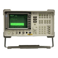
HP 8563A Service Manual (446 pages)
Spectrum Analyzer
Brand:
HP
| Category:
Measuring Instruments
| Size: 48.22 MB
Table of Contents
Table of Contents
7
General Information
19
Manual Organization
19
Manual Text Conventions
20
Serial Numbers
20
Instrument Variations
21
Serial Number Label Example
21
HP 85629B Test and Adjustment Module
22
Service Kit
22
Recommended Test Equipment
22
Electrostatic Discharge
23
Reducing Potential for ESD Damage
23
Example of a Static-Safe Work Station
23
Static Safe Accessories
24
Static-Safe Accessories
24
Returning Instruments for Service
25
Service Tag
25
Original Packaging
25
Other Packaging
25
HP8563A Shipping Container and Cushioning Materials
26
Sales and Service Offices
27
Hewlett-Packard Sales and Service Offices
28
Recommended Test Equipment
29
Adjustment Procedures
36
Introduction
36
Safety Considerations
37
Which Adjustments Should be Performed
37
Test Equipment
37
Adjustable and Factory-Selected Components
37
Adjustment Tools
38
Instrument Service Position
38
High-Voltage Power Supply Adjustment
39
Display Adjustment
40
Adjustable Components
41
Using the TAM
44
Test Equipment
44
Adjustment Indicator
45
IF Bandpass Adjustment
45
IF Amplitude Adjustment
45
Sampling Oscillator Adjustment
45
YTO Adjustment
45
Dual Band Mixer Bias Adjustment
45
Frequency Response Adjustment
45
Required Test Equipment for TAM
46
High-Voltage Power Supply
47
High-Voltage Power Supply Adjustment Setup
47
Display Adjustment
49
Display Adjustment Setup
49
IF Bandpass Adjustment
53
IF Bandpass Adjustment Setup
53
Factory-Selected LC Filter Capacitors
55
LC Factory-Selected Capacitor Selection
55
Factory-Selected XTAL Filter Capacitors
56
XTAL Factory-Selected Capacitor Selection
56
Capacitor Part Numbers
57
IF Amplitude Adjustment
58
IF Amplitude Adjustment Setup
58
Sampling Oscillator Adjustment
62
Sampling Adjustments
66
YTO Adjustment
67
7. 1ST lo Distribution Amplifier Adjustment
70
1St lo Distribution Amplifier Adjustment Setup
70
Dual Band Mixer Bias Adjustment
72
Dual Band Mixer Bias Adjustment Setup
72
A8 Bias Voltage
73
Frequency Response Adjustment
74
Frequency Response Adjustment Setup
74
10. Calibrator Amplitude Adjustment
77
Calibrator Amplitude Adjustment Setup
77
11. 10 Mhz Reference Adjustment-OCXO
79
10 Mhz Reference Adjustment Setup and Adjustment Location
80
Mhz Reference Adjustment-TCXO (Option 103 Only)
82
13. Demodulator Adjustment
84
Demodulator Adjustment Setup
84
14. External Mixer Bias Adjustment
87
External Mixer Bias Adjustment Setup
87
15. External Mixer Amplitude Adjustment
89
External Mixer Amplitude Adjustment Setup
89
Conversion Loss Data
90
16. Second if Gain Adjustment
92
A15U802 Values
94
SIG Ill Oscillator Adjustment
95
18. YTF Adjustment
98
YTF Adjustment Setup
98
Assembly Replacement
101
Access to Internal Assemblies
102
Cable Color Code
102
Required Tools
102
Procedure 1. Analyzer Cover Assembly
103
HP 8563A Hinged Assemblies
103
Procedure 2. A1 Front Frame/A18 CRT
104
A9, A18, and Line-Switch Assembly Mounting Screws
107
Front-Frame Mounting Screws
108
Procedure 3. A1A1 Keyboard/Front Panel Keys
112
Key Positions as Viewed from Inside
113
Procedure 4. A1A2 RPG (Rotary Pulse Generator)
114
Procedure 5. A2, A3, A4, and A5 Assemblies
115
Assembly Cables
117
Coaxial Cable Clip
119
Procedure 6. A6 Power Supply
121
A6 Power Supply Connections
122
A6 Power Supply Cover
123
Procedure 7. A6A1 Idgh Voltage Assembly
124
A17 CRT Driver Mounting Screws
125
A16 Cable Routing
126
Procedure 8. A7 through A13 Assemblies
127
Assembly Locations
128
Procedure 830.A7 1St lo Distribution Amplifier
130
Procedure 8B. A8 Dual Band Mixer
131
Procedure 8C. A9 Input Attenuator
132
A9 Mounting Screws at Right Frame
132
Procedure 8D. A10 YTF
133
Procedure 8E. All YTO
134
Procedure 8F. A12 RF Switch
135
Procedure 8G. A13 Second Converter
138
Procedure 9. A14 Frequency Control and A15 RF Assemblies
139
Procedure 10. A16 CAL Oscillator/ A17 CRT Driver
142
Procedure 11. B1 Fan
144
Procedure 12. Btl Battery
145
Procedure 13. Rear Frame/Rear Dress Panel
146
Procedure 14. W3 Line Switch Cable
150
Procedure 15. EEROM (A2U501)
157
Procedure 16. A21 OCXO
159
Replaceable Parts
161
Ordering Information
161
Direct Mail Order System
161
Firmware-Dependent Part Numbers
161
Direct Phone-Order System
162
Parts List Format
162
Firmware-Dependent Part Numbers
162
Replaceable Parts
170
Major Assembly and Cable Locations
190
Introduction
190
Assembly-Level Text
202
Block Diagrams
202
Assembly Test Points
202
Test Point Pads
202
Test Jack (Connectors)
202
Ribbon Cables
202
Troubleshooting to a Functional Section
208
Using the TAM
210
TAM Requirements
211
Test Connectors
211
Revision Connectors
211
Inconsistent Results
211
Erroneous Results
212
Automatic Fault Isolation
212
Controller Check
212
2. Adcfinterface Check
212
IF Flog Check
212
LO Control Check
213
RF Check
213
Manual Probe Troubleshooting
213
RF Path Fault Isolation
214
Error Messages
215
Viewing Multiple Messages
215
Error Message Elimination
216
System Errors (200 to 201)
217
ADC Errors (250 to 251)
217
YTO Loop Errors (300 to 301)
218
Roller PLL Errors (302 to 316)
218
YTO Loop Errors (317 to 318)
220
Roller Oscillator Errors (321 to 329)
220
YTO Loop Errors (331)
221
YTO Loop Errors
221
600 Mhz Reference Loop (333)
222
YTO Leveling Loop (334)
222
Sampling Oscillator (335)
222
Automatic if Errors (400 to 599)
222
600 Mhz Reference Loop
222
YTO Leveling Loop
222
Sampling Oscillator
222
EEROM Checksum Errors (700 to 704)
231
Program ROM Check-Sum Errors (705 to 708)
232
Program ROM Checksum Errors (705 to 708)
232
RAM Check Errors (713 and 714)
232
Microprocessor Error (717)
232
Battery Problem (718)
232
Model Number Error (719)
232
Microprocessor Error
232
Battery Problem
232
Model Number Error
232
System Errors (750 to 757)
233
Module Errors (800 to 899)
233
User-Generated Errors (902 to 904)
233
Block I>Iagram I>Escription
234
RF Section
234
A9 Input Attenuator
235
A10 Ytf
235
A12 RF Switch
235
A13 Second Converter
235
Third Converter (Part of A15)
236
Automatic Fault Isolation References
251
TAM Tests Versus A3 Test Connectors
252
Demultiplexer A3U410 Truth Table
274
Demultiplexer A3U500 Truth Table
274
Automatic Fault Isolation References
278
IF Section
278
Troubleshooting A4 with the TAM
278
Troubleshooting A5 with the TAM
278
TAM Tests Versus Test Connectors
279
Troubleshooting A16 with the TAM
282
Sweep Width Settings
283
Automatic if Adjustment
283
Parameters Adjusted
284
Requirements
285
Performance Test Failures
285
Signal Level for Reference Level Display
286
Scale Fidelity Performance Test
287
Resolution Bandwidths Performance Tests
287
A4 Log Amplifier Assembly
287
Log Amplifier
288
Linear Amplifiers
289
Detector
290
Differential Amplifier
290
Video Offset
291
Frequency Counter Prescaler/Conditioner
292
TAM Tests Versus Test Connectors
319
Automatic Fault Isolation References
344
Automatic Fault Isolation References
345
TAM Tests Versus Test Connectors
346
Sweep Signal Destination Versus Span
350
Harmonic Mixing Number Versus Center Frequency
350
Settings of Sweep Switches
352
Settings for Switches and Comparators
357
YTO Frequency Errors with A14J23 on Pins 2 and
363
Voltages in FM Coil and Main Loop Drivers
365
Sampling Oscillator PLL Divide Ratios
375
Automatic Fault Isolation References
392
Sweep + Tune Multiplier Values
405
Advertisement
HP 8563A Operating Note (5 pages)
Resistive divider kit
Brand:
HP
| Category:
Laboratory Equipment
| Size: 1.25 MB
Advertisement
Related Products
HP 8153A
HP HP 81551MM
HP HP 81552SM
HP HP 81553SM
HP 8560A
HP Elitebook 8560W
HP HP 8566B
HP 8569A
HP 85688
HP 8565A
HP Categories
Desktop
Laptop
Server
Monitor
Switch
More HP Manuals
Login
Sign In
OR
Sign in with Facebook
Sign in with Google
Upload manual
Upload from disk
Upload from URL