Sign In
Upload
Manuals
Brands
Mitsubishi Electric Manuals
Air Conditioner
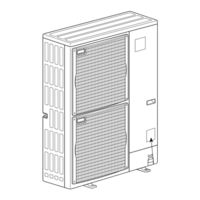
City Multi PUMY-P48NHMU2
Mitsubishi Electric City Multi PUMY-P48NHMU2 Manuals
Manuals and User Guides for Mitsubishi Electric City Multi PUMY-P48NHMU2. We have
1
Mitsubishi Electric City Multi PUMY-P48NHMU2 manual available for free PDF download: Technical & Service Manual
Mitsubishi Electric City Multi PUMY-P48NHMU2 Technical & Service Manual (101 pages)
SPLIT-TYPE, HEAT PUMP AIR CONDITIONERS
Brand:
Mitsubishi Electric
| Category:
Air Conditioner
| Size: 7.88 MB
Table of Contents
Table of Contents
1
Determine Required Indoor Fans Speed During Defrost Mode
2
Outdoor Unit DIPSW4-4 for Primary Heating Control
2
Primary Heating On/Off Control Set-Up
2
Technical Changes
2
Determine Fan Airflow Setting During Indoor Thermo off Conditions
3
Setting Outdoor Unit and Auxiliary Heat Switch over Temperatures
3
Locally Procured Wiring
4
Recommended Circuit
4
Additional Refrigerant Charge
5
Cautions for Service
5
Cautions Related to New Refrigerant
5
Safety Precaution
5
Service Tools
6
Cautions for Refrigerant Piping Work
7
Dimensions of Flare Cutting and Flare Nut
7
Thickness of Pipes
7
Tools for R410A
7
Overview of Units
8
Unit Construction
8
Method for Identifying MULTI-S Model
9
Operating Temperature Range
9
Unit Specifications
9
Specifications
10
Capacity of Indoor Unit
12
Cooling and Heating Capacity and Characteristics
12
Data
12
Method for Obtaining System Cooling and Heating Capacity
12
Standard Capacity Diagram
13
Capacity Correction Factor Curve
15
Cooling Performance Curve
15
Correcting Changes in Air Conditions
15
Correcting Cooling and Heating Capacity
15
Correcting Capacity for Changes in the Length of Refrigerant Piping
16
Correction of Heating Capacity for Frost and Defrosting
16
Method for Obtaining the Equivalent Piping Length
16
Noise Criterion Curves
17
Outlines and Dimensions
18
Caution for Electrical Work
20
Cautions When Servicing
20
Wiring Diagram
20
Necessary Conditions for System Construction
24
Transmission System Setup
24
Refrigerant Pipng Specifications
25
Refrigerant System Diagram
25
Group Operation
26
Operation Using 2 Remote Controllers
26
Standard Operation
26
System Control
26
Longest Transmission Cable Length
27
Remote Controller Cable Length
27
Name, Symbol, and the Maximum Units for Connection
29
Example of a MA Remote Controller System
30
Check Points for Test Run
34
Procedures of Test Run
34
Troubleshooting
34
Completing Normal Entry
35
Making Paired Settings
35
Paired Settings
35
Special Function Operation and Settings (for M-NET Remote Controller)
35
Address Check
36
Display after Address Has Been Cleared Normally
36
Countermeasures for Error During Test Run
37
Remote Controller Diagnosis
53
Remote Controller Trouble
54
Internal Switch Function Table
56
Auto Change over (CN3N)
58
Outdoor Unit Input/Output Connector
58
State (CN51)
58
How to Check the Parts
59
Check Method of Multi Controller Board
61
Check Method of Power Board
62
Circuit Diagram
62
Check Method of Noise Filter Circuit Board
63
Check Method of ACTM
64
Check Method of M-NET Transmission Power Board
65
High Pressure Sensor
66
How to Check the Components
66
Low Temperature Thermistors
66
Medium Temperature Thermistor
66
Outdoor Multi Controller Board
67
Test Point Diagram
67
Outdoor Power Circuit Board
68
Transmitting Signal to the Outdoor Controller Circuit Board
68
Outdoor Noise Filter Circuit Board
69
Transmission Power Board
71
Active Filter Module
72
Connection and Internal Circuit Diagram
72
Tester Check Points of Acive Filter Module
72
Outdoor Unit Functions
74
Electrical Wiring
81
Overview of Power Wiring
81
Power Supply Wire Diameter and Capacity
81
Wiring Diagram for Main Power Supply
81
Design for Control Wiring
82
Example External Wiring Diagram for a Basic System
82
Selection Number of Control Wires
82
System Switch Setting
82
Method of Obtaining System Power Factor
83
Method of Obtaining Total Current
83
Procedure for Obtaining Total Power Consumption
83
Refrigerant Piping Tasks
84
Select each Section of Refrigerant Piping
84
Selecting the Refrigerant Branch Kit
84
Confirming Procedure of R410A Concentration
87
Maximum Concentration
87
Precautions against Refrigerant Leakage
87
Disassembly Procedure
88
Removing the Electrical Parts Box
88
Removing the Fan Motor (MF1, MF2)
88
Removing the Service Panel and Top Panel
88
Remove Electrical Parts Box Fixing Screw
89
Removing the Thermistor
89
Removing the 4-Way Valve
90
Removing the 4-Way Valve Coil (21S4)
90
Removing Bypass Valve Coil(SV1) and Bypass Valve
91
Removing the High Pressure Sensor (63HS)
91
Removing the Accumulator
92
Removing the Compressor (MC)
92
Parts List
93
Structural Parts
93
Functional Parts
94
Rohs PARTS LIST
96
Optional Parts
99
Advertisement
Advertisement
Related Products
Mitsubishi Electric PUMY-P48NHMU
Mitsubishi Electric PUMY-P48NHMU-BS
Mitsubishi Electric City Multi PUMY-P48NHMU1
Mitsubishi Electric City Multi PUMY-P48NHMU1-BS
Mitsubishi Electric City Multi PUMY-P48NHMU2-BS
Mitsubishi Electric PUMY-P48NKMU2
Mitsubishi Electric PUMY-P48NKMU3
Mitsubishi Electric PUMY-P48NKMU3-BS
Mitsubishi Electric PUMY-P48NKMU4
Mitsubishi Electric PUMY-P48NKMU2-BS
Mitsubishi Electric Categories
Air Conditioner
Controller
Projector
Inverter
Heat Pump
More Mitsubishi Electric Manuals
Login
Sign In
OR
Sign in with Facebook
Sign in with Google
Upload manual
Upload from disk
Upload from URL