Mitsubishi Electric MTA-150HRN1 Manuals
Manuals and User Guides for Mitsubishi Electric MTA-150HRN1. We have 1 Mitsubishi Electric MTA-150HRN1 manual available for free PDF download: Technical Manual
Mitsubishi Electric MTA-150HRN1 Technical Manual (167 pages)
R410A Tropical Split Type AC
Brand: Mitsubishi Electric
|
Category: Air Conditioner
|
Size: 5.67 MB
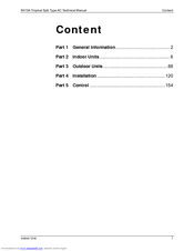
Table of Contents
Advertisement
Advertisement
Related Products
- Mitsubishi Electric MTA-150CRN1
- Mitsubishi Electric MTA-76CRN1
- Mitsubishi Electric MTA-96CRN1
- Mitsubishi Electric MTA-120CRN1
- Mitsubishi Electric MTA-76HRN1
- Mitsubishi Electric MTA-96HRN1
- Mitsubishi Electric MTA-120HRN1
- Mitsubishi Electric MSZ-GC35VA
- Mitsubishi Electric MUZ-A09NA- U2
- Mitsubishi Electric MUX-20TV - E1