Sign In
Upload
Manuals
Brands
Motorola Manuals
Portable Radio
Astro XTS 4000
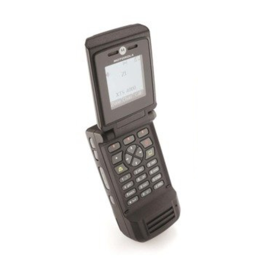
Motorola Astro XTS 4000 Portable Radio Manuals
Manuals and User Guides for Motorola Astro XTS 4000 Portable Radio. We have
3
Motorola Astro XTS 4000 Portable Radio manuals available for free PDF download: Service Manual, User Manual
Motorola Astro XTS 4000 Service Manual (128 pages)
Brand:
Motorola
| Category:
Portable Radio
| Size: 10.33 MB
Table of Contents
Foreword
4
Manual Revisions
4
Computer Software Copyrights
4
Document Copyrights
4
Disclaimer
4
Trademarks
4
Document History
5
Table of Contents
7
List of Tables
11
Commercial Warranty
14
Limited Warranty
14
Motorola Communication Products
14
What this Warranty Covers and for How Long
14
II. General Provisions
14
III. State Law Rights
15
IV. How to Get Warranty Service
15
What this Warranty Does Not Cover
15
VI. Patent and Software Provisions
16
VII. Governing Law
16
Model Numbering, Charts, and Specifications
17
Portable Radio Model Numbering System
17
ASTRO XTS 4000 VHF Model Chart
18
ASTRO XTS 4000 UHF Model Chart
19
Specifications for VHF Radios
20
Specifications for UHF Range 1 Radios
21
Chapter 1 Introduction
23
Manual Contents
23
Notations Used in this Manual
23
Radio Description
24
Flashport
24
Table 1-1. ASTRO XTS 4000 Basic Features
24
Chapter 2 Basic Maintenance
25
General Maintenance
25
Handling Precautions
25
General Repair Procedures and Techniques
26
Table 2-1. Lead Free Solder Wire Part Number List
26
Table 2-2. Lead Free Solder Paste Part Number List
26
Chapter 3 Basic Theory of Operation
29
Major Assemblies
29
Figure 3-1. XTS 4000 Overall Block Diagram
29
Digital Mode of Operation
30
Figure 3-2. Receiver Block Diagram
30
Main Board
31
Table 3-1. Local Oscillator and First if Frequencies
31
Figure 3-3. Transceiver (VHF) Block Diagram (Power and Control Omitted)
31
Chapter 4 Recommended Test Equipment and Service Aids
33
Recommended Test Equipment
33
Table 4-1. Recommended Test Equipment
33
Service Aids
34
Field Programming
34
Table 4-2. Service Aids
34
Chapter 5 Performance Checks
35
Test Equipment Setup
35
Figure 5-1. Performance Checks Test Setup
35
Display Radio Test Mode
36
Table 5-1. Initial Equipment Control Settings
36
Table 5-2. Test-Mode Displays
37
Table 5-3. Test Frequencies (Mhz)
38
Rf Test Mode
38
Table 5-4. Test Environments
39
Receiver Performance Checks
41
Table 5-5. Receiver Tests for ASTRO Conventional Channels
41
Transmitter Performance Checks
43
Table 5-6. Transmitter Tests for ASTRO Conventional Channels
43
Chapter 6 Radio Alignment Procedures
45
Test Setup
45
Figure 6-1. Radio Alignment Test Setup
45
Tuner Main Menu
46
Figure 6-2. Tuner Software Main Menu
46
Softpot
47
Figure 6-3. Typical Softpot Screen - VHF
47
Figure 6-4. Typical Softpot Screen - UHF
47
Radio Information
48
Reference Oscillator Alignment
48
Figure 6-5. Radio Information Screen
48
Figure 6-6. Reference Oscillator Alignment Screen - VHF
49
Table 6-1. Reference Oscillator Alignment
50
Figure 6-7. Reference Oscillator Alignment Screen - UHF
50
Transmit Power Alignment
51
Figure 6-8. Battery Eliminator with RF Connector and SMA
51
Table 6-2. Transmit Power Settings
52
Figure 6-9. Transmit Power Alignment Screen (Typical) - VHF
52
Figure 6-10.Transmit Power Alignment Screen (Typical) - UHF
52
Transmit Deviation Balance Alignment
53
Figure 6-11. Transmit Deviation Balance Alignment Screen - VHF
54
Figure 6-12.Transmit Deviation Balance Alignment Screen - UHF
54
Transmit Deviation Limit Alignment
55
Figure 6-13.Transmit Deviation Limit Alignment Screen - VHF
56
Figure 6-14.Transmit Deviation Limit Alignment Screen - UHF
56
Front End Filter Alignment
57
Figure 6-15.Battery Eliminator with RF Connector and SMA
57
Figure 6-16.Front End Filter Alignment Screen - VHF
58
Figure 6-17.Front End Filter Alignment Screen - UHF
58
6.10 Bit Error Rate
59
6.11 Transmitter Test Pattern
60
Figure 6-18.Bit Error Rate Screen
60
Figure 6-19.Transmitter Test Pattern Screen - VHF
61
Figure 6-20.Transmitter Test Pattern Screen - UHF
61
Chapter 7 Encryption
63
Load an Encryption Key
63
Multikey Feature
63
Select an Encryption Key
63
Select an Encryption Index
64
Erase an Encryption Key
65
Table 7-1. Encryption Key Zeroization Options
66
Chapter 8 Disassembly/Reassembly Procedures
67
XTS 4000 Exploded View (Partial)
67
Table 8-1. Corresponding XTS 4000 Exploded View and Parts List
68
Figure 8-1. XTS 4000 Partial Exploded View
68
Required Tools and Supplies
69
Fastener Torque Chart
69
Table 8-2. Required Tools and Supplies
69
Table 8-3. Fastener Torque Chart
69
Antenna
70
Figure 8-2. Attaching the Antenna
70
Figure 8-3. Removing the Antenna
70
Battery
71
Figure 8-4. Attaching the Battery
71
Radio Disassembly
72
Figure 8-5. Removing the Battery
72
Figure 8-6. Separating Flip-Front Housing Assembly from Chassis Assembly
73
Figure 8-7. Unplugging Flexes
74
Figure 8-8. Disconnecting CE-UCM Connector Flex and Lifting Main Board
74
Figure 8-9. Rotating Main Board 90° and Unplugging Top Control Inner Jumper Flex
75
Figure 8-10.Removing Control Band
76
Figure 8-11. Removing Audio Jack Dust Cover
76
Figure 8-12.Removing CE Dust Cover
77
Figure 8-13.Removing Audio Jack
77
Figure 8-14.Removing CE Retainer and Spacer
78
Figure 8-15.Removing CE Board
78
Figure 8-16.Disassemble Speaker Compartment Seal, Main Keyboard and UCM Board
79
Figure 8-17.Separating Keypad Backer Inner Jumper Flex
80
Figure 8-18.Removing Secure Pad
80
Figure 8-19.Removing Front Housing from Flip Assembly
81
Figure 8-20.Removing Tabs from Flip Stopper Pad
81
Figure 8-21.Removing Microphone Boot and Microphone from Front Housing
82
Figure 8-22.Separating Hinge from Flip Inner Housing
82
Radio Reassembly
83
Figure 8-23.Removing CID Bezel
83
Figure 8-24.Flip Flex
84
Figure 8-25.Inserting Flip Flex
85
Figure 8-26.Tongue in CID Bezel into Flip Sub-Assembly
85
Figure 8-27.Adhere Flip Flex into Front Housing
86
Figure 8-28.Reassemble UCM Board
87
Figure 8-29.Attach Secure Pad to Keypad Backer Sub-Assembly
87
Figure 8-30.Reassemble Flip Flex
88
Figure 8-31.Assemble T6 Screws to Front Housing
88
Figure 8-32.Assemble T6 Screws to Front Housing
89
Figure 8-33.Inserting Spacer to CE Retainer
89
Figure 8-34.Reassemble CE Retainer and Spacer
90
Figure 8-35.Reassemble Flip Flex
90
Figure 8-36.Slide Audio Jack Insulator into Chassis
91
Figure 8-37.Reassemble CE Connector Dust Cover
91
Figure 8-38.Assemble Audio Jack Dust Cover
92
Figure 8-39.Adhere Assembly Aid
92
Figure 8-40.Reassemble Control Band
93
Figure 8-41.Assemble B Plus Seal to B Plus Connector
94
Figure 8-42.Assemble B Plus Seal to B Plus Connector
94
Figure 8-43.Holding CE-UCM Flex
95
Figure 8-44.Reassemble Flexes
95
Servicing CID Bezel Only
96
Figure 8-45.Screws Reassemble Sequence
96
Chapter 9 Basic Troubleshooting
97
Power-Up Error Codes
97
Table 9-1. Power-Up Error Code Displays
97
Operational Error Codes
98
Receiver Troubleshooting
98
Table 9-2. Operational Error Code Displays
98
Table 9-3. Receiver Troubleshooting Chart
98
Transmitter Troubleshooting
99
Table 9-4. Transmitter Troubleshooting Chart
99
Encryption Troubleshooting
100
Table 9-5. Encryption Troubleshooting Chart
100
Chapter 10 Exploded Views and Parts Lists
101
Table 10-1. XTS 4000 Exploded Views and Parts Lists
101
Exploded View and Parts List - Main Assemblies
102
Figure 10-1.Exploded View - Main Assemblies
102
Table 10-2. Parts List - Main Assemblies
102
Exploded View and Parts List - Flip-Front Housing Assemblies
103
Figure 10-2.Exploded View - Flip - Front Housing Assemblies
103
Table 10-3. Parts List - Flip-Front Housing Assemblies
103
Table 10-5. Service Kit Table
103
Exploded View and Parts List - Chassis Assembly
104
Figure 10-3.Exploded View - Chassis Assembly
104
Table 10-4. Parts List - Chassis Assembly
104
Parts List - Service Kit
105
Appendix A Accessories
107
Antennas
107
Batteries and Battery Accessories
107
Carry Accessories
107
Chargers
107
Surveillance Accessories
108
Appendix B Replacement Parts Ordering
109
Basic Ordering Information
109
Motorola Online
109
Mail Orders
109
Telephone Orders
109
Fax Orders
110
Parts Identification
110
Product Customer Service
110
Appendix C Motorola Service Centers
111
Servicing Information
111
Motorola Service Center
111
Motorola Federal Technical Center
111
Motorola Canadian Technical Logistics Center
111
Glossary
113
Advertisement
Motorola Astro XTS 4000 User Manual (55 pages)
Brand:
Motorola
| Category:
Portable Radio
| Size: 3.16 MB
Table of Contents
Declaration of Conformity
4
Computer Software Copyrights
5
General Radio Operation
8
Physical Features of the XTS 4000 Radio
9
Display
10
Adjusting the Display Brightness
11
Status Icons
11
Menu Entry Features
15
Home Button
15
Programmable Buttons
16
Way Navigation Button
16
Alert Tones
18
Standard Accessories
21
Zones and Channels
22
Receive / Transmit
23
Common Radio Features
24
Radio Lock
25
Ring Style
27
Loudspeaker
28
Conventional Squelch Operation
29
Time-Out Timer
30
Emergency
31
Send an Emergency Call
32
Send a Silent Emergency Alarm
32
Site View and Change
33
Ars User Login and Text Messaging Features
34
Lists
35
ARS User Login and Text Messaging Features
36
Text Messaging
37
Compose a New Text Message
40
Send a Predefined Message
43
Edit a Quick Text Message
44
Reply to a Received Message
44
Delete a Message
45
To Access the Draft Folder
46
To Access the Sent Folder
46
Radio Care
47
Service
49
Charging the Battery
50
Battery Recycling and Disposal
51
Accessories
53
Batteries and Battery Accessories
54
Motorola Astro XTS 4000 User Manual (49 pages)
Brand:
Motorola
| Category:
Portable Radio
| Size: 3.68 MB
Table of Contents
Table of Contents
5
General Radio Operation
7
Notations Used in this Manual
7
Your XTS 4000 Radio
8
Physical Features of the XTS 4000 Radio
9
Programmable Controls
9
Display
10
Keypad
16
Alert Tones
18
Standard Accessories
21
Radio on and off
23
Set the Volume
23
Zones and Channels
24
Receive / Transmit
26
Common Radio Features
27
Transmit Power Level
27
Radio Lock
28
Ring Style
30
Audio Selection
31
Conventional Squelch Operation
32
Time-Out Timer
33
Emergency
34
Lists
37
Scan
42
Telephone Calls (Trunking Only)
44
Private Calls (Trunking Only)
47
Advertisement
Advertisement
Related Products
Motorola ASTRO XTS 4250
Motorola ASTRO Digital XTS 3000
Motorola ASTRO XTS 2500I Model 1
Motorola ASTRO XTSTM 2500
Motorola ASTRO XTS-5000
Motorola ASTRO XTS 2500 Model 1
MOTOROLA ASTRO XTS 25003
Motorola ASTRO XTS 5000 I
Motorola ASTRO XTS 5000 II
Motorola ASTRO XTS 3500
Motorola Categories
Cell Phone
Two-Way Radio
Baby Monitor
Cordless Telephone
Radio
More Motorola Manuals
Login
Sign In
OR
Sign in with Facebook
Sign in with Google
Upload manual
Upload from disk
Upload from URL