Sign In
Upload
Manuals
Brands
Philips Manuals
TV
47PFL9532/9x_2
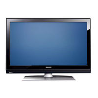
User Manuals: Philips 47PFL9532/9x_2 Smart LED TV
Manuals and User Guides for Philips 47PFL9532/9x_2 Smart LED TV. We have
1
Philips 47PFL9532/9x_2 Smart LED TV manual available for free PDF download: Service Manual
Philips 47PFL9532/9x_2 Service Manual (216 pages)
Brand:
Philips
| Category:
TV
| Size: 49.82 MB
Table of Contents
Table of Contents
1
Colour Television
1
Display Supply (32"): Part
1
1 Technical Specifications, Connections, and Chassis Overview
2
Display Supply (32"): Part
2
Rear Connectors
3
Connection Overview
3
Side Connections
3
Chassis Overview
4
PWB/CBA Locations 32" Sets
4
PWB/CBA Locations 42" ME7 Styling Sets
4
PWB/CBA Locations 42" Aurea Styling Sets
5
PWB/CBA Locations 47" Sets
5
Lead-Free Soldering
6
2 Safety Instructions, Warnings, and Notes
6
3 Directions for Use
7
Alternative BOM Identification
7
Board Level Repair (BLR) or Component Level Repair
7
Practical Service Precautions
7
4 Mechanical Instructions
8
Cable Dressing
8
Cable Dressing 32" Sets
8
Cable Dressing 42” ME7 Styling Sets
9
Cable Dressing 42" Aurea Styling Sets
9
Service Positions
10
Foam Bars
10
Aluminium Stands
10
Assy/Panel Removal ME7 Styling
11
Rear Cover
11
Rear Cover Removal
11
Side I/O Board
12
Keyboard Control Board
12
IR & LED Board
12
Speakers
12
Display Supply Panel - 42" Sets
13
Display Supply Panel - 47" and 52" Sets
13
Dynamic Frame Insertion Panel (DFI)
13
Small Signal Board (SSB)
14
Ambilight Unit
14
LCD Panel
14
Assy/Panel Removal Aurea Styling
17
Stand Removal
18
Ambilight Reflector and Low-Range Speaker Removal
18
Ambilight LED Panel Removal
19
Subframe Removal
20
Rim Removal
21
Tweeters Removal
22
Power Supply Unit (PSU)
23
Audio and Ambilight Supply Panel
24
Set Re-Assembly
24
5 Service Modes, Error Codes, and Fault Finding
25
Test Points
25
Service Default Mode (SDM)
25
How to Activate SDM
25
How to Activate SAM
26
Contents of SAM
26
How to Navigate
26
How to Exit SAM
26
Customer Service Mode (CSM)
27
Contents of CSM
27
Stepwise Start-Up
29
Transition Diagram
29
Off/Stby to Semi
30
Service Tools
39
Error Codes
39
Compair
39
How to Read the Error Buffer
39
Error Buffer
40
Error Code Overview
40
Extra Info
40
The Blinking LED Procedure
41
Protections
41
Fault Finding and Repair Tips
41
Ambilight
41
Csm
42
DC/DC Converter
42
Exit “Factory Mode”
43
Sanken Display Supply
43
SSB Service Supply Connector
43
Tuner
43
SSB Replacement
44
Display Option Code
45
Upgrade EDID NVM
45
Software Upgrading
45
Main Software Upgrade
45
Automatic Software Upgrade
46
Manual Software Upgrade
46
Back-Up Software Upgrade Application
46
Stand-By Software Upgrade
47
Content and Usage of the One-Zip Software File
47
Upgrade Via USB
47
Upgrade Via PC and Compair Interface
47
6 Block Diagrams, Test Point Overview, and Waveforms
49
Wiring Diagram 32” LCD
49
Wiring Diagram 42” LCD
50
Wiring Diagram 47”
51
Wiring Diagram 42” (AUREA)
52
Block Diagram Supply 32”
53
Block Diagram Supply 37” - 42”
54
Block Diagram Supply 47”
55
Block Diagram Supply Audio & Ambilight
56
Block Diagram Video
57
Block Diagram Audio
58
Block Diagram Control & Clock Signals
59
SSB: Test Points (Overview Top Side)
60
Testpoint Overview Small Signal Board
60
Test Points (Part 1 Top Side)
61
SSB: Test Points (Overview Bottom Side)
63
SSB: Test Points (Part 1 Bottom Side)
64
I2C IC Overview
66
Supply Lines Overview
67
7 Circuit Diagrams and PWB Layouts
68
(A1)
68
(A2)
69
Layout Display Supply Panel (32”) (Top Side)
70
Layout Display Supply Panel (32”) (Bottom Side)
71
Display Supply (42”): Mains Filter & Standby
72
Display Supply (42"): Supply (A2)
73
Display Supply (42"): DC - DC (A3)
73
Display Supply (42”): DC - DC
74
Layout Display Supply (42”) (Top Side)
75
Layout Display Supply (42”) (Bottom Side)
76
DFI Panel: DC - DC (AB1)
77
DFI Panel: Video Flow (AB2)
78
DFI Panel: Clock (AB3)
79
DFI Panel: Supply (AB4)
80
DFI Panel: FPGA: Power & Control (AB5)
81
DFI Panel: FPGA: DFI (AB6)
82
DFI Panel: DDR a
83
(Ab7)
83
DFI Panel: DDR B
84
(Ab8)
84
DFI Panel: Display Interfacing
85
(Ab9)
85
DFI Panel: FPGA Ambilight
86
(Ab10)
86
Layout DFI Panel (Top Side)
87
Layout DFI Panel (Bottom Side)
88
Ambilight Panel (5 LED)
89
(Al1)
89
(Al2)
90
Layout Ambilight Panel (5 LED) (Overview Top Side)
91
Layout Ambilight Panel (5 LED) (Part 1 Top Side)
91
Layout Ambilight Panel (5 LED) (Part 2 Top Side)
91
Ambilight Panel (3 Side 4 LED)
92
(Al1)
92
(Al2)
93
Audio & al Supply Panel: Supply
95
(Ap1)
95
Audio & al Supply Panel: Audio
96
(Ap2A)
96
Audio & al Supply Panel: Protection
97
(Ap2B)
97
Audio & al Supply Panel: Subwoofer
98
(Ap2C)
98
Audio & al Supply Panel: Centre Input (AP2D)
99
Layout Audio & Ambilight Supply Panel (Top Side)
100
Layout Audio & Ambilight Supply Panel (Bottom Side)
101
SSB: Supply
102
Ssb: DC / DC
104
SSB: Channel Decoder
107
SSB: Main Tuner
108
SSB: Pnx85Xx: Standby Controller
109
SSB: Pnx85Xx: Debug
110
SSB: Pnx85Xx: NVM / UART Switch
110
SSB: Pnx85Xx: Miscellaneous
111
SSB: Pnx85Xx: Control
112
SSB: Pnx85Xx: SDRAM
114
SSB: Pnx85Xx: Digital Video in
115
SSB: Pnx85Xx: Audio
116
SSB: Pnx85Xx: Analogue AV
117
SSB: Pnx85Xx: Video Streams
120
SSB: Pnx85Xx: Digital Video
121
SSB: Pnx85Xx: Power
122
SSB: Pnx85Xx: Flash
123
SSB: PNX5050: Control
124
Ssb: Pnx5050: Sdram
125
SSB: PNX5050: Video
126
SSB: PNX5050: Supply
127
SSB: Pacific 3: LVDS
128
SSB: Pacific 3: Display & Interfacing
129
SSB: Pacific 3
130
Ssb: Uart
131
Ssb: Spdif
132
Ssb: Hdmi
134
SSB: Debug
135
SSB: HDMI Switch
136
SSB: Analogue Externals
137
Ssb: Usb 2.0
139
SSB: LED Panel Connector
141
SSB: Audio Left / Right
142
SSB: Audio Protection/Mute Control
143
SSB: SRP List Explanation
144
Non-SRP Schematics
144
Power Supply Lines
144
Normal Signals
144
SSB: SRP List
145
Layout Small Signal (Overview Top Side)
147
(B1-B11) 102-143
147
Layout Small Signal (Part 1 Top Side)
148
Layout Small Signal (Overview Bottom Side)
150
Side Facing Side Av
153
Side I/O Panel
153
Layout Side I/O Panel (Bottom Side)
154
Layout Side I/O Panel (Top Side)
154
Keyboard Control Panel
155
Layout Keyboard Control Panel (Bottom Side)
156
Layout Keyboard Control Panel (Top Side)
156
Keyboard Control Panel (Aurea)
157
Layout Keyboard Control Panel (Aurea) (Bottom Side)
157
Layout Keyboard Control Panel (Aurea) (Top Side)
157
Front IR / LED Panel
158
Layout Front IR / LED Panel (Bottom Side)
159
Layout Front IR / LED Panel (Top Side)
159
IR & LED Panel (Aurea)
160
Layout IR & LED Panel (Aurea) (Bottom Side)
160
Layout IR & LED Panel (Aurea) (Top Side)
160
8 Alignments
161
General Alignment Conditions
161
Software Alignments
161
White D Alignment Values
161
Option Settings
162
Tint Settings
162
Service Options
162
Dealer Options
162
Opt. No. (Option Numbers)
163
Option Code Overview
163
Reset of Repaired SSB
163
9 Circuit Descriptions, Abbreviation List, and IC Data Sheets
164
Features
164
Architecture of TV520 Platform
165
TV520 Architecture Overview
165
SSB Bottom View
166
SSB Cell Layout
166
SSB Top View
166
Platform Power Management
167
32" Sets
168
Block Diagram Display Supply 32" Sets
168
Display Supply
168
Power-Good Circuitry
168
42” Sets
169
47" Sets
170
Audio Class-D Amplifiers
170
Aurea Sets
170
On-Board Platform Supply
170
On-Board DC/DC Converters
171
Output Voltage Control
171
Peak Current Control
171
Reduced / Maximum Power Mode
171
1.2V and 3.3V DC/DC Converters
172
Front-End
172
PWM Generator and MOSFET Drivers
172
Voltage Booster
172
Analogue Signal Processing (Front-End)
173
Device Specifications
173
Master if (TDA9898)
173
Tuner (TD1716)
173
PAL/SECAM Video Broadcast Reception Block Diagram
174
PAL/SECAM Audio Broadcast Reception Block Diagram
175
Pnx85Xx
176
Pnx85Xx Video Flow Diagram
176
Video Subsystem
176
Audio Subsystem
177
Audio-Video Codec Subsystem
177
Pnx85Xx Audio Flow Diagram
177
Back-End
178
Back-End Key Component Overview
178
Control and Compute Subsystem
178
Full-HD Sets @ 50 / 100 Hz
179
HD Sets @ 50 / 100 Hz
179
Full-HD Sets @ 100 Hz - Dynamic Frame Insertion
180
Pnx5050
181
Pacific 3 (T6Tf4Hfg)
182
PACIFIC 3 CMOS + LVDS Interface
182
PACIFIC 3 Control (Diagram B06C)
182
Ambient Light
183
Dynamic Frame Insertion (DFI) Panel
183
Two Sided Ambilight Addressing
183
Four Sided Pixelated Ambilight Addressing
184
Three Sided Ambilight Addressing
184
Three Sided Ambilight Byte Selection
184
Two Sided Ambilight Byte Selection
184
Abbreviation List
185
IC Data Sheets
188
Internal Block Diagram and Pin Configuration
188
Diagram B03B, TDA9898HL (IC 7T57)
191
Diagram B08E, AD8191ASTZ (IC 7J27)
195
Diagram B10A, ISP1562BE (IC 7N00)
196
10 Spare Parts and Diversity List
197
11 Revision List
215
Advertisement
Advertisement
Related Products
Philips 47PFL9532/9x_1
Philips 47PFL4007T
Philips 47PFL8008G
Philips 47PFL6158S/12
Philips 47PFL7108S/60
Philips 47PFL7704D/F7B
Philips 47PFL3007K/12
Philips 47PFL7007G/77
Philips 47PFL5007G/78
Philips 47PFL3605/98
Philips Categories
TV
Monitor
Stereo System
Electric Shaver
CD Player
More Philips Manuals
Login
Sign In
OR
Sign in with Facebook
Sign in with Google
Upload manual
Upload from disk
Upload from URL