Sign In
Upload
Manuals
Brands
Toshiba Manuals
All in One Printer
E-studio506
Toshiba E-studio506 Manuals
Manuals and User Guides for Toshiba E-studio506. We have
4
Toshiba E-studio506 manuals available for free PDF download: Service Manual, Management Manual, Scanning Manual, Safety Information Manual
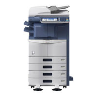
Toshiba E-studio506 Service Manual (1524 pages)
MULTIFUNCTIONAL DIGITAL SYSTEMS
Brand:
Toshiba
| Category:
All in One Printer
| Size: 65.27 MB
Table of Contents
Service Manual
1
General Precautions Regarding the Service for this Equipment
3
Transportation/Installation
3
General Operations
4
General Precautions at Service
4
Important Service Parts for Safety
4
Cautionary Labels
5
Disposal of the Equipment
5
Table of Contents
11
1 Features
23
2 Specifications / Accessories / Options / Supplies
25
Copy
28
Dimensions of the Equipment
28
Copy Speed
29
Print
34
E-Filing
35
Network Fax
36
Accessories
37
Options
38
System List
40
E-STUDIO206L/256/306
40
E-STUDIO356/456
41
E-STUDIO506
42
E-STUDIO207L/257/307
44
E-STUDIO357/457/507
45
Supplies
47
3 Outline of the Machine
49
Sectional View
49
Electric Parts Layout
54
Scanner Unit, Control Panel
54
Laser Unit, Fuser Unit, Toner Cartridge
57
Drive Unit
59
Drawer Unit
66
Symbols and Functions of Various Components
67
Motors
67
Sensors and Switches
67
Electromagnetic Clutches
69
PC Boards
70
Solenoids
70
Lamps and Heaters
71
Thermistors and Thermostats
71
Others
72
Transformer
72
Copy Process
73
General Description of Copying Process
73
Comparison with E-STUDIO205L/255/305/355/455
74
Comparison with E-STUDIO206L/256/306/356/456/506
76
General Operation
78
Description of Operation
78
Overview of Operation
78
Warming-Up
78
Drawer Feed Copying
79
Bypass Feed Copying
80
Interruption Copying
80
Description of Abnormality
81
Detection of Abnormality
81
Types of Abnormality
81
Hibernation Function
86
Control Panel
87
General Description
87
Description of Operation
88
Structure
88
Scanner
89
Construction
91
Functions
92
Original Glass
92
Carriage-1
92
Exposure Lamp (EXP)
92
Carriage-2
93
Lens Unit
94
CCD Driving PC Board (CCD)
94
Scanning Section Control PC Board
94
System Control PC Board (SYS Board)
94
Lamp Inverter Board (INV) / LED Board (LEDB)
95
Scanning Operation
96
Process of Detection of Original Size
96
Scanning of an Original Placed on the Original Glass
96
Scanning of an Original Placed on the RADF
96
Description of Operation
96
Sensor Detection Points
97
Laser Optical Unit
99
Laser Precautions
100
Paper Feeding System
101
Sectional View of Paper Feeding Section (Front Side)
101
Paper Feeding Section Drive System (Rear Side)
102
Composition
103
Functions
104
Bypass Feeding Mechanism
106
Operation
106
Operation of Drawer Pickup Roller
106
Operation of Clutch
107
Separation of Paper
107
Bypass Feeding
108
From Power-ON to Ready Status
108
Paper Feeding
108
Ready Status
108
Upper Drawer
109
Drive System
110
Functions
111
Drum Related Section
112
Configuration
112
Drum
113
Main Charger
113
Drum Cleaner
113
Cleaning Blade
113
Functions
113
Transfer Roller Unit
114
Discharge LED
114
Drum Thermistor
114
High-Voltage Transformer
114
Development System
115
Developer Material
116
Developer Unit
116
Functions
116
Toner Cartridge Drive Unit
116
Toner Cartridge Installation Detection Mechanism (IC Chip)
116
Recovered Process Unit Mechanism
117
Recovered Toner Supply Mechanism
118
Fuser Unit
119
Functions
121
Fuser Roller
121
Heater Lamp
121
Pressure Roller
121
Separation Fingers
121
Operation
122
Heater Control Circuit
123
Paper Exit Section/Reverse Section
124
Exit Motor (M10)
125
Exit Roller
125
Functions
125
Reverse Sensor (S23) (Only Installed for E-STUDIO356/456/506
125
Exit Motor
126
Reverse Motor
126
Offset Gate Motor
127
Automatic Duplexing Unit (Adu)
128
Description of Operations
129
Functions
129
Drive of ADU
130
Power Supply Unit
131
AC Filter
131
DC Output Circuits
131
Heater Lamp Control Circuit
131
Operation of DC Output Circuits
132
Output Protection
132
Starting Line Output
132
Stopping Line Output
132
Sleep Mode
133
Super Sleep Mode
133
Output Channel
134
Linked with the Door Switch
135
Not Linked with the Door Switch
135
Output Connector
135
Fuse
138
4 Disassembly and Replacement
141
Disassembly and Replacement of Covers
141
Front Cover
141
Front Upper Cover
141
Front Lower Cover
142
Rear Cover
143
Right Upper Cover
143
Inner Tray
144
Left Rear Cover
144
Upper Rear Cover
144
Connecting Port Cover
145
Left Cover
145
Tray Back Cover
145
Right Rear Cover-1
146
Right Rear Cover-2
146
Fig
147
Left Front Cover
147
Right Front Cover
147
Disassembly and Replacement of Covers <E-STUDIO207L/257/307/357/457/507>
148
Fig
148
Paper Exit Cover
148
Front Upper Cover
150
Left Upper Cover
151
Rear Cover
152
Left Rear Cover-1
153
Tray Back Cover
154
Right Rear Cover-1 / Right Rear Cover-2
155
Left Front Cover
156
Paper Exit Cover
157
CONTROL PANEL <E-STUDIO206L/256/306/356/456/506>
158
Stopper
158
Display Board (DSP)
160
KEY Board (KEY)
161
Touch Panel (TCP)
161
Control Panel Cover
162
KEY Board
163
DSP Board
164
Touch Panel
165
Lens Cover
166
SCANNER <E-STUDIO206L/256/306/356/456/506>
166
Automatic Original Detection Sensor (S1/S2/S3/S4/S5)
167
Exposure Lamp (EXP)
168
Lens Unit
171
Scan Motor (M1)
175
Carriage-1
176
Lamp Inverter Board (INV)
179
Installing the Lamp Harness
180
LED Board (LEDB)
182
Carriage Wire / Carriage-2
183
Platen Sensor (S6) / Carriage Home Position Sensor (S7)
184
SLG Board (SLG)
184
SCANNER <E-STUDIO207L/257/307/357/457/507>
185
Automatic Original Detection Sensor-1
186
Lens Unit / CCD Driving PC Board
187
Carriage Home Position Sensor
188
Exposure Lamp
189
Scan Motor (M1)
190
Platen Sensor-1, -2(S21, S22)
191
Carriage-1
192
Carriage Wire, Carriage-2
195
Installing the Carriage Wire
196
Winding on the Wire Pulley
197
LASER OPTICAL UNIT <E-STUDIO206L/256/306/356/456/506>
198
LASER OPTICAL UNIT <E-STUDIO207L/257/307/357/457/507>
200
Drawer
203
Drawer Feeding Unit
203
Paper Feeding System
203
Empty Sensor (S17/S20)
204
Tray-Up Sensor (S16/S19)
204
Paper Stock Sensor (S15/S18)
205
Separation Roller
205
Feed Roller
206
Pickup Roller
207
Drawer Feed Clutch (CLT4/CLT5)
208
Bypass Tray
209
Paper Width Detection PC Board (SFB)
210
Bypass Feed Unit
211
Bypass Separation Pad
212
Bypass Paper Sensor (S12)
213
Registration Guide
214
Registration Sensor (S22)
214
1St Transport Sensor (S21))
215
Transport Roller
216
2Nd Transport Sensor (S14)
217
Feed Cover Opening/Closing Detection Sensor (S13)
217
Flywheel (E-STUDIO206L/256/306 / 207L/257/307)
217
Flywheel (E-STUDIO356/456/506 / 357/457/507)
218
Registration Roller Clutch (CLT2)
218
Upper Tray-Up Motor (M11)
219
Hi-Speed Clutch (CLT6) / Low-Speed Clutch(CLT7)
220
Upper Drawer Detection Switch (SW6)
220
Lower Drawer Detection Switch (SW7)
221
Lower Tray-Up Motor (M12)
222
Registration Roller (Rubber)
223
Registration Roller (Metal)
224
Drive System
225
Main Motor (M8)
225
Toner Motor (M4)
225
Main Motor Drive Unit
226
Process Unit Fan (M2) <E-STUDIO207L/257/307/357/457/507>
227
Drum Cleaner Unit
228
Drum Related Section
228
Process Unit
228
Discharge LED
230
Main Charger
231
Main Charger Cleaner
232
Main Charger Grid
232
Needle Electrode
232
Drum
233
Drum Cleaning Blade
234
Drum Separation Finger
234
Ozone Filter
235
Recovery Blade
235
TRU Fan (M9)
236
Transfer Roller Unit
237
Separation Needle
238
Transfer Roller
238
Temperature/Humidity Sensor (S25)
239
Transfer Unit
239
Development System
240
Auto-Toner Sensor (S8)
243
Drum Thermistor (THMS4)
243
Guide Roller / Developer Sleeve
244
Mixer
248
Fuser Roller
254
Heater Lamp
255
Center / Side / Edge Thermistor (THMS1/THMS2/THMS3)
257
Fuser Center / Fuser Front Thermostat (THMO1/THMO2)
258
Pressure Roller
260
Reverse Unit
264
Paper Exit Unit
265
Exit Roller
267
Offset Gate Motor (M13)
272
Upper Transport Roller
273
ADU Clutch (CLT1)
279
ADU Lower Transport Roller
281
ADU Upper Transport Roller
281
Installation and Replacement of Options
283
Mr-3021/3022/3028
283
KD-1025 (Paper Feed Pedestal (PFP))
285
KD-1026 (Large Capacity Feeder (LCF))
287
MJ-1032 (Finisher)
289
MJ-1033 (Finisher)
292
MJ-1101/1107 (Finisher)
295
MJ-1106/1108 (Finisher)
296
KN-2520 (Bridge Unit)
298
Damp Heater Kit (MF-4550U/E) Installation Procedure
305
Preparation
305
Damp Heater Kit (MF-5070U/E) Installation Procedure
318
5 Self-Diagnosis Modes
333
Exiting from each Mode
333
List of Modes
333
Starting each Mode
333
State Transition Diagram of Self-Diagnosis Modes
334
About each Mode
335
EPU Replacement Mode (7S)
336
Password Reset Mode (489)
336
PM Support Mode (6S)
336
Login Procedure
337
Service UI
337
In the Security Mode
338
Setting/Changing Password
339
[SERVICE MODE] Screen
339
Input Check (Test Mode 03)
340
Output Check (Test Mode 03)
341
Test Print Mode (Test Mode 04)
341
Operation Procedure in Adjustment Mode (05)
342
Operation Procedure in Setting Mode (08)
344
Test Print Pattern in Adjustment Mode (05)
344
Assist Mode (3C)
346
Encryption Key / License Backup/Restoring (Key Backup Restore)
346
HDD Partition Creation (Formant HDD)
346
SRAM Data Format (Clear SRAM)
346
HDD Securely Erasing (Erase HDD Securely)
347
SRAM Securely Erasing (Erase SRAM Securely)
347
SRAM Service Tech Password Formatting (Clear Service Tech Password)
347
Operating Procedure of Assist Mode
348
HDD Assist Mode (4C)
349
When a Normal HDD Is Mounted
350
Functions
351
Revert Factory Initial Status HDD
351
Remove Key
352
File System Recovery Mode (5C)
353
Check of the File System (Check F/S)
354
Explanation for each Item
354
Functions
354
Recovery of the File System (Recovery F/S)
354
Initialize the DB (Initialize DB)
355
Initialize the File System (Initialize HDD)
355
Displaying Usage Rate of each Partition
356
Displaying Various Data in the HDD
356
SRAM Clear Mode (6C)
358
Clear SRAM
359
Functions
359
Reset Date and Time
359
Set Serial Number
359
SRAM Re-Initialize Support
359
List Print Mode (9S)
360
CSV Output
360
Print Output
360
List Printing
361
PM Support Mode
363
Setting Mode (08)
363
Stored Information of Pixel Counter (Service Technician Reference)
364
Stored Information of Pixel Counter (Toner Cartridge Reference)
364
Error History
365
Firmware Update Log
366
Power ON/OFF Logs Are Output
367
Power-ON/OFF Log
367
Version List
368
Total Counter List
369
Factors Affecting Toner Consumption
371
Outline
371
Pixel Counter and Its Related Code
371
Details of Pixel Counter
372
Factors Affecting Toner Consumption and the Tendency
372
Toner Cartridge Reference
372
Print Count (Number of Output Pages)
373
Service Technician Reference
373
Average Pixel Count (%)
374
Average Pixel Count (%) and Latest Pixel Count (%)
374
Latest Pixel Count (%)
374
Type of Calculated Data
374
Pixel Count and Number of Output Pages Per Cartridge
375
Relation between Pixel Count and Toner Consumption
375
Display on LCD Screen
376
Information Screen of Toner Cartridge Reference
376
Pixel Counter Confirmation
376
Information Screen of Service Technician Reference
377
Data List of Toner Cartridge Reference
378
Data List Printing
378
Data List of Service Technician Reference
379
Pixel Count Code Table
379
Pixel Count Distribution
380
Service Technician Reference Cleared Date
380
Table 5-203 Pixel Count Code Table
380
Toner Cartridge Reference Count Started Date
380
6 Setting / Adjustment
381
Adjustment Order
381
Adjustment of Auto-Toner Sensor
382
Image Dimensional Adjustment
384
Procedure to Key in Adjustment Values
385
Paper Alignment at the Registration Roller
386
Grid Pattern
388
Printer Related Adjustment
388
Primary Scanning Data Laser Writing Start Position (Printer)
389
Reproduction Ratio of Secondary Scanning Direction
390
Secondary Scanning Data Laser Writing Start Position
391
Adjustment for Long-Sized Paper
392
Adjustment for Short-Sized Paper
392
Primary Scanning Data Laser Writing Start Position at Duplexing
392
Adjustment Procedure Summarization for a to E
393
Adjustment Screw for the Mirror-3 (Rear)
394
Image Distortion
394
Scanner Related Adjustment
394
Reproduction Ratio Adjustment of the Primary Scanning Direction
395
Image Position Adjustment of the Primary Scanning Direction
396
Reproduction Ratio Adjustment of the Secondary Scanning Direction
397
Image Position Adjustment of the Secondary Scanning Direction
398
Top Margin
399
Right Margin
400
Bottom Margin
401
Image Quality Adjustment (Copying Function)
402
Automatic Gamma Adjustment
402
Density Adjustment
403
Background Adjustment
405
Sharpness Adjustment
405
Adjustment of Smudged/Faint Text
406
Setting Range Correction
406
Gamma Balance Adjustment
407
Adjustment of Image Density
408
Background Offsetting Adjustment for RADF
409
Judgment Threshold Adjustment for Blank Originals
409
RADF Scan Noise Reduction (Copying Function)
409
Image Quality Adjustment (Printing Function)
410
Adjustment of Image Density
411
Gamma Balance Adjustment
412
Image Quality Adjustment (Scanning Function)
413
Density Adjustment
414
Judgment Threshold for ACS
415
Setting Range Correction
416
Background Adjustment
417
Fine Adjustment of Black Density
418
Background Processing Offset Adjustment
419
Adjustment of the Capacity and Image Quality of Slimpdf
420
Surrounding Void Amount Adjustment
421
JPEG Compression Level Adjustment
421
RADF Scan Noise Reduction (Scanning Function)
422
Image Quality Adjustment (FAX Function)
423
Adjustment of Image Density
424
Adjustment of High-Voltage Transformer
425
Installation of the High-Voltage Transformer Jig
426
Connection for Developer Bias Adjustment
428
Connection for Main Charger Adjustment
428
Connection for Separation Charger Adjustment
429
Developer Bias
431
Precautions
431
Transfer
431
When Blotched Image Appear
431
Items to Check before Adjustment
432
When Poor Paper Separation Occurs
432
When Poor Transfer Occurs
432
Adjustment of the Scanner Section
433
Carriages
433
Installing Carriage Wires
433
Adjusting Carriages - 1 and 2 Positions
434
Assembling Carriage Wires
435
3-Line CCD
437
4-Line CCD
437
Replacing the Lens Unit
437
Adjustment of the Magnification Ratio of the Lens
439
Adjustment of the Paper Feeding System
442
Sheet Sideways Deviation Caused by Paper Feeding
442
Drawer Feeding
443
Adjustment of Developer Unit
445
Doctor-To-Sleeve Gap
445
Adjustment of Dogleg
448
Adjustment of the RADF
450
Adjustment of RADF Position
450
Adjustment of RADF Height
456
Adjustment of Skew
458
Duplex Copying
458
Simplex Copying
458
Adjustment of the Leading Edge Position
461
Adjustment of Horizontal Position
463
Adjustment of Copy Ratio
464
Adjustment of RADF Opening/Closing Sensor (MR-3021/3022 Only)
465
Adjustment of the Finisher (MJ-1032)
466
Alignment Position Adjustment (Front)
466
Alignment Position Adjustment (Rear)
466
Stapling Position Adjustment
466
Punching Position Center Adjustment
467
Stapling Position Adjustment (Center 2-Point)
467
Stapling Position Adjustment (Front 1-Point / “R” Series Size)
467
Stapling Position Adjustment (Front 1-Point)
467
Punch Hole Position Adjustment
468
Adjustment of the Finisher (MJ-1033)
469
Saddle Stitch Folding Position Adjustment
469
Saddle Stitching Position Adjustment
469
Alignment Position Adjustment
470
Punching Position Center Adjustment
471
Gripper Arm Exiting Position Adjustment
472
Saddle Stitch Alignment Position Adjustment
472
Height/Skew Adjustment
473
Adjustment of the Finisher (MJ-1101/1107)
475
Adjusting the Alignment Position
475
Adjusting the Stapling Position
477
B4-Size Recycled Paper Mode Settings
479
B4-Size Recycled Paper Mode
480
Normal Mode
480
Adjusting Paper Exit Speed
481
DIP Switch Settings
481
Connection Model Settings
482
Mode Settings
482
Paper Type Settings
482
Paper Size Settings
483
Setting List
483
Normal Paper Mode
484
Paper Exit Speed Settings
484
Recycled Paper Mode
485
Paper Exit Tray Switching Settings
486
Adjustment of the Finisher (MJ-1106/1108)
488
Adjusting the Stapling Position
491
Stapling/Folding Position Adjustment in Saddle Stitch Unit
493
Saddle Stitch Skew Adjustment
499
Adjustment of Hole Punch Unit (MJ-6007)
500
Adjustment of Hole Punch Unit (MJ-6008)
501
Registration of the Number of Punch Holes
504
7 Preventive Maintenance (Pm)
507
PM Display
507
PM Display Conditions
507
Counter Indicating Current Number of Prints and Driving Time
508
Setting Value Which Determines the Display Conditions
508
Clearing Counter
509
PM Display Contents
509
General Descriptions for PM Procedure
510
Operational Flow and Operational Screen
511
PM Support Mode Activated
511
Main Screen
512
Sub Screen
513
Clear Screen
514
LCD Screen Display List
515
Check the Drive Counts of All Parts at PM Support Mode
516
When the Number of Output Pages Has Reached the Specified Level
516
Work Flow of Parts Replacement
516
EPU Replacement Mode (7S)
517
Counters to be Cleared
519
After Replacement
520
Fuser Unit Status Detection Mode
521
Preventive Maintenance Checklist
522
Symbols/Values Used in the Checklist
522
E-STUDIO206L/256/306/356/456/506
523
E-STUDIO207L/257/307/357/457/507
523
Scanner
523
Laser Optical Unit
524
Paper Feeding Section
525
Registration Roller (Pusher)
526
Drive Gears in the Paper Feeding Section
527
Drum Related Section
528
Developer Section
530
During Replacement, Coat the Oil Seal with Grease
531
Oil Seal
531
Fuser Unit
532
Paper Exit Section / Reverse Section
534
Automatic Duplexing Unit
535
Pfp (Kd-1025)
536
Lcf (Kd-1026)
537
Job Separator (MJ-5004)
538
Offset Tray (MJ-5005)
539
Finisher (MJ-1032)
540
Radf (Mr-3021/3022/3028)
540
Finisher (MJ-1033)
541
Finisher (MJ-1101/1107)
542
Buffer Tray Shaft
543
Paper Holder Cam
543
Movable Tray Drive Gear
544
Rack Gear, Pinion Gear (Aligning Plate)
544
Stapler Carrier Shaft
544
Buffer Tray Guide
545
Finishing Tray Shaft
545
Finisher (MJ-1106/1108)
546
Paper Pusher Cam
547
Grate-Shaped Guide
550
Hole Punch Unit (MJ-6103/6104)
551
Precautions for Storing and Handling Supplies
552
Checking and Cleaning of Photoconductive Drum
553
Use of Gloves
553
Handling Precautions
553
Installation of the Equipment and Storage of Drum
553
Checking and Cleaning of Drum Cleaning Blade
554
Checking and Replacing the Transfer Roller
555
Pm Kit
556
Maintenance Part List
557
Grease List
559
Operational Items in Overhauling
559
Machine Refreshing Checklist (E-STUDIO207L/257/307/357/457/507)
560
Symbols/Value Used in the Checklist
560
Advertisement
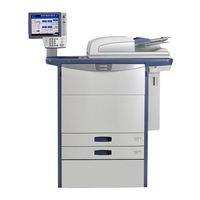
Toshiba E-studio506 Management Manual (192 pages)
MULTIFUNCTIONAL DIGITAL COLOR SYSTEMS / MULTIFUNCTIONAL DIGITAL SYSTEMS
Brand:
Toshiba
| Category:
All in One Printer
| Size: 15.78 MB
Table of Contents
Preface
3
Table of Contents
5
Chapter 1 SETTING ITEMS (USER)
10
Accessing the User Menu
10
General
11
Changing the Display Language
11
Setting the Reversed Display
12
Adjusting the Display Setting
12
Setting the Auto Calibration
12
Setting the Calibration
12
Setting the Registration
13
Copy
14
Fax
15
Scan
16
E-Filing
18
List
19
Drawer
20
Address
22
Managing Contacts in Address Book
22
Managing Groups in Address Book
32
Check E-Mail
44
Print
45
Change User Password
46
Chapter 2 SETTING ITEMS (ADMIN)
49
Accessing the Admin Menu
49
General
51
Setting the Device Information
52
Setting the Notification
53
Changing the Administrator Password and Resetting the Service Password
54
Setting the Clock
55
Setting the Energy Saver Modes
57
Setting the Auto Power Save Mode
58
Setting the Calibration and Registration Display Level
60
Setting the Calibration
60
Changing the Smoothness of Print
61
Setting the Registration
61
Setting the Status Message
62
Setting the Auto Clear Function
62
Managing the Option Licenses
62
Adding or Removing Display Languages
65
Updating Your System
68
Creating or Installing Clone Files
71
Setting the Panel Calibration
76
Exporting Logs
76
Setting Job Skip
77
Changing the Keyboard Layout
78
Cleaning the Main Chargers and LED Print Heads
79
Setting the Pop-Up Messages
79
Setting the Option
79
Network
80
Setting the TCP/IP Protocol (Ipv4)
80
Setting the TCP/IP Protocol (Ipv6)
82
Setting the IPX/SPX Protocol
88
Setting the Netware Settings
89
Setting the SMB Protocol
90
Setting the Appletalk Protocol
91
Setting the HTTP Network Service
92
Setting the Ethernet Speed
93
Setting the LDAP Services and the Filtering Functions
94
Setting Ipsec (IP Security)
95
Checking the Network
96
Copy
98
Fax
100
Setting the Discard and Reduction Print Option for RX Print
100
File
101
E-Mail
102
Internet Fax
104
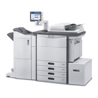
Toshiba E-studio506 Scanning Manual (134 pages)
MULTIFUNCTIONAL DIGITAL COLOR SYSTEMS / MULTIFUNCTIONAL DIGITAL SYSTEMS
Brand:
Toshiba
| Category:
All in One Printer
| Size: 9.97 MB
Table of Contents
How to Read this Manual
3
Symbols in this Manual
3
Table of Contents
5
Chapter 1 OVERVIEW
8
Scan Features
8
Scan Functions
8
Scan to File
10
Scan Speed
13
Templates
15
Internet Fax Features
16
Chapter 2 BASIC OPERATION
20
Viewing Touch Panel for Scan Menu
20
Default Settings
22
Scan to E-Filing
23
Scan to File
24
Scan to E-Mail
33
Scan to USB
40
Web Service (WS) Scan
45
Using Saved Scan Data
47
Using Scan Data Saved as E-Filing Documents
47
Using Scan Data Saved as Files
47
Viewing the Scan Job Status and Log
49
Viewing the Scan Job Status
49
Viewing the Scan Job Log
50
Chapter 3 Useful Functions
51
Changing Scan Settings
52
Specifying Color Mode
52
Specifying Resolution
53
Selecting Original Mode
53
Changing Orientation
55
Scanning 2-Sided Originals
56
Specifying Original Size
57
Changing Compression Ratio
58
Removing Blank
58
Erasing Black Frames Around Images
59
Adjusting Exposure
61
Adjusting Contrast
61
Adjusting Background Density
61
Adjusting Sharpness
62
Adjusting Color Balance
62
Rgb Adjustment
62
Reducing ADF Scan Noise
63
Previewing Scans
64
Specifying E-Mail Addresses
66
Scanning with Dual Functions (Dual Agents)
81
Encrypting PDF Files
84
Chapter 4 USING TEMPLATES
87
Registering Scan Templates
88
Using Scan Templates
94
Advertisement
Toshiba E-studio506 Safety Information Manual (36 pages)
MULTIFUNCTIONAL DIGITAL COLOR SYSTEMS
Brand:
Toshiba
| Category:
All in One Printer
| Size: 7.01 MB
Table of Contents
Safety Information
1
Table of Contents
2
Preface
3
End User Software License Agreement
5
Security Precautions
7
Notice to Users
9
Toshiba Quality Is Second to None
13
How to Read this Manual
19
Symbols in this Manual
19
Chapter 1 GENERAL PRECAUTIONS
21
General Precautions
21
When Installing or Moving
21
When Using the Multifunctional Digital Systems
25
During Maintenance or Inspection
31
When Handling Supplies
31
Chapter 2 ENVIRONMENTAL INFORMATION
33
Environmental Information
33
ENERGY STAR ® Program
33
Turkey Rohs Compliance
33
Advertisement
Related Products
Toshiba E-studio506se
Toshiba e-STUDIO506L
Toshiba e-STUDIO5055C Series
Toshiba E-studio5055cse
Toshiba e-STUDIO507 Series
Toshiba e-STUDIO5008A Series
Toshiba e-STUDIO50
Toshiba e-Studio5008LP
Toshiba e-STUDIO5015AC
Toshiba e-STUDIO5018A
Toshiba Categories
Laptop
Air Conditioner
TV
LCD TV
All in One Printer
More Toshiba Manuals
Login
Sign In
OR
Sign in with Facebook
Sign in with Google
Upload manual
Upload from disk
Upload from URL