
Related Manuals for Honeywell ECC-50/100


Summary of Contents for Honeywell ECC-50/100
- Page 1 Emergency Command Center ECC-50/100 ECC-50/100E Instruction Manual Document LS10001-000FL-E 5/3/2016 Rev: P/N LS10001-000FL-E:G ECN 16-212...
- Page 2 Fire Alarm & Emergency Communication System Limitations While a life safety system may lower insurance rates, it is not a substitute for life and property insurance! An automatic fire alarm system—typically made up of smoke (caused by escaping gas, improper storage of flammable materi- detectors, heat detectors, manual pull stations, audible warning als, etc.).
- Page 3 LiteSpeed™ and Lite-Connect™ are trademarks; and Fire-Lite® Alarms and SWIFT® are registered trademarks of Honeywell International Inc. Microsoft® and Windows® are registered trademarks of the Microsoft Corporation. Chrome™ and Google™ are trademarks of Google Inc.
- Page 4 •Brief description of content you think should be improved or corrected •Your suggestion for how to correct/improve documentation Send email messages to: FireSystems.TechPubs@honeywell.com Please note this email address is for documentation feedback only. If you have any technical issues, please contact Technical Services.
-
Page 5: Table Of Contents
Table of Contents Section 1: Product Description ..................... 12 1.1: Product Features ............................12 1.2: Input/Output Circuit Specifications ......................14 1.2.1: ECC-50/100 Main Control Board .....................14 1.2.2: Display Board ............................18 1.2.3: ECC-CE6 Circuit Expander Module ....................19 1.3: Controls and Indicators..........................20 1.3.1: Push-Button Controls ........................20 1.3.2: LED Indicators (visible with door closed) ..................21... - Page 6 Table of Contents Section 3: Programming ......................59 3.1: ECC-50/100 Panel Installation/Maintenance Security Checklist ..............60 3.2: Main Menu - User Programming .........................60 3.2.1: Password Options ..........................61 3.2.2: General/NAC Options ........................61 General Options ............................61 NAC Options ............................63 Console Control ............................63 3.2.3: Address Assignment ..........................64 Remote Microphone / Operator Console Address Assignments ............64...
- Page 7 Appendix B: Wiring Requirements..................101 Appendix C: Canadian Applications ................... 103 C.1: Audio Room Isolator Modules........................103 C.1.1: Description............................103 C.1.2: Panel Programming.........................103 C.1.3: Applications ............................104 Slide-in Labels........................105 Index............................109 ECC-50/100 and ECC-LOC OPERATING INSTRUCTIONS ..........113 Emergency Command Center Manual — P/N LS10001-000FL-E:G 5/3/2016...
- Page 8 This control panel has been designed to comply with standards set forth by the following regulatory agencies: • Underwriters Laboratories/Underwriters Laboratories Canada • National Fire Protection Association Before proceeding, the installer should be familiar with the following documents. NFPA Standards This Fire Alarm Control Panel complies with the following NFPA Standards: NFPA 72 National Fire Alarm Code Note: Audible signal appliances used in public mode applications, are required to have...
- Page 9 FI RE S YSTE M ACTIVE S Y S TEM CALL CO NTROL ® by Honeywell TB24 TB12 ® external battery by Honeywell distributed TB22 audio charger - J7 ECC-125DA...
- Page 10 Emergency Command Center Manual — P/N LS10001-000FL-E:G 5/3/2016...
- Page 11 Basic System Connections - Display Board (Section 1.2.2) JP2 - External Data Bus termination JP5 - isolation/ground when powered by source other than main control board SW1- Dipswitch for BUS addressing J2- Connection to main control board External Audio Input/ TB5- Audio Riser SW2- Distributed Audio Switch...
-
Page 12: Section 1: Product Description
The ECC-50/100 comes standard with one speaker circuit. The panel provides the ability to record fourteen field programmable messages (up to 60 seconds each) with an integral microphone or from an external audio source. - Page 13 – eight Style Y (Class B) or Style Z (Class A) speaker circuits (with optional ECC-50W- 25/70V and ECC-CE6 installed) • ECC-50/100 can be controlled by an FACP via the ANN/ACS (EIA-485) link. Compatible FACPs include the MS-9600(UD)LS and MS-9200UDLS. •...
-
Page 14: Input/Output Circuit Specifications
1.2 Input/Output Circuit Specifications 1.2.1 ECC-50/100 Main Control Board AC Power - TB15 ECC-50/100: 120 VAC, 60 Hz, 3.5 amps (HOT, NEU) ECC-50/100E: 240 VAC, 50 Hz, 2.0 amps (HOT=HotLeg1, NEU=HotLeg2) Wire size: minimum #14 AWG (2.00mm ) with 600 V insulation. - Page 15 Product Description Input/Output Circuit Specifications Speaker Circuits Primary Speaker Circuit - TB20, Terminals 1(+) & 2(-) Style Y (Class B), 4(+) & 5(-) Style Z (Class A), 3 Shield (Standby and Alarm Polarity Shown) on main control board Secondary Speaker Circuit (with optional amplifier only) - TB21, Terminals 1(+) & 2(-) Style Y (Class B), 4(+) &...
- Page 16 Product Description Input/Output Circuit Specifications External Data Bus (EIA-485) - TB12, Terminals 2 (B), 3 (A), 4 (BRTN), 5 (ARTN), & 1 (SHLD) Data connections for external operator interface components Redundant transceiver circuitry for Class A operability Power-limited (Class 2) circuitry, supervised Maximum wiring impedance: 13.2 Ω...
- Page 17 Product Description Input/Output Circuit Specifications Current Availability The following figures illustrate the maximum current allowed for each output circuit in the panel and the total output current available from the power supply. Refer to Section 6, “Power Supply Calculations” for additional current draw by option cards that must be considered when determin- ing total standby and alarm currents.
-
Page 18: 2: Display Board
Product Description Input/Output Circuit Specifications TB20 10W max. = 0.66 Primary 50W amps from supply Speaker Circuit TB24 External Operator 0.8 amp max. Interface Power TB17 Aux. Power 0.5 amp max. Alarm 7.5 amps max. TB19 2.0 amps max. NAC Circuit TB20 TB23 Primary 50W... -
Page 19: 3: Ecc-Ce6 Circuit Expander Module
Product Description Input/Output Circuit Specifications 1.2.3 ECC-CE6 Circuit Expander Module Power-limited (Class 2) circuitry Up to six (6) circuits on the ECC-CE6 can be wired as Style Y (Class B) or Style Z (Class A). Normal Operating Voltage for Speaker Circuits: 25 V @ 2 amps max. -
Page 20: Controls And Indicators
RM 1 NAC ACTIVE DIST. AMP 7 RM 2 SYSTEM TROUBLE DIST. AMP 8 RM 3 AUDIO RISER FAULT yellow green Figure 1.4 ECC-50/100 Keypad 1.3.1 Push-Button Controls • • MNS Control • System Control • Speaker Select 1-24 •... -
Page 21: 2: Led Indicators (Visible With Door Closed)
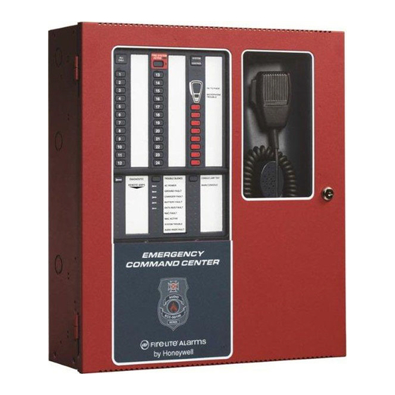
– Short circuit on volume control module 1.4 Components Main Control Board The ECC-50/100 main control board contains the system's CPU, power supply, battery charger, other primary components and wiring interface components. One 50W amplifier is integrated into the main control board. - Page 22 FIRE SYSTEM ACTIVE SYSTEM CALL CONTROL ® by Honeywell Figure 1.5 Cabinet Batteries The cabinet provides space for up to 18 Amp Hour batteries (charged by integral Power Sup- ply/Battery Charger) with all options installed. Dress Panel The Dress Panel is supplied standard with the system. It mounts to the cabinet with two supplied screws.
-
Page 23: Optional Equipment
ECC-50W-25/70V Audio Amplifier Modules An optional second audio amplifier can be plugged into connectors J10 & J11 located in the upper right of the main control board in the ECC-50/100. This amplifier also provides 50 watts of power at 25 V... - Page 24 ALL CALL broadcast of a stored message can be done by pressing a message button. The message buttons operate in the same fashion as the message buttons on the ECC-50/100 main console. Not for use in UL2572 Mass Notification or Canadian applications.
-
Page 25: Ul 464 Low Frequency Sounders
Amplifiers: Amplifier/Audio Product Description ECC-50/100 Main console ECC-50/100 with ECC-50W-25V Main console with optional second 25V amplifier installed ECC-50/100 with ECC-XRM-70V Main console with 70V transformer installed ECC-50/100 with ECC-XRM-70V Main console with 70V transformer and optional second 70V amplifier... -
Page 26: Section 2: Installation
Section 2: Installation 2.1 Mounting Options The cabinet may be semi-flush or surface mounted. The cabinet mounts using three key slots at the top of the backbox and two additional 0.250" diameter holes located at the bottom. Carefully unpack the system and check for shipping damage. Mount the cabinet in a clean, dry, vibration-free area where extreme temperatures are not encountered. -
Page 27: Removing The Chassis Assembly
Installation Backbox Installation Lift the dress panel up and gently pull the lower hinge out of the backbox. Gently pull down to remove the top hinge. Store the dress panel in a safe place. unplug cable ECC-MCB-PCA Rev. loosen screws TB15 RTZM dress panel... -
Page 28: Mounting The Backbox
Installation Backbox Installation Mounting the Backbox Mark and predrill hole in the wall for the center top keyhole mounting bolt using the dimen- sions illustrated in Figure 2.4 on page 29. Install center top fastener in the wall with the screw head protruding. Place backbox over the top screw, level and secure. - Page 29 Installation Backbox Installation Semi-Flush Mounting Do not recess box more Hinge Slot for than 3.875” into wall to Dress Panel avoid covering venting holes on top of box. Do not use these knock-outs! Mounting slots for optional Trim Ring Semi-flush mounting hole Hinge Slot for Dress Panel...
- Page 30 Installation Backbox Installation Depth Depth = Door Backbox FIRE SYSTEM ACTIVE SYSTEM CALL CONTROL Door Backbox ® by Honeywell Left Side Right Side Bottom Figure 2.5 ECC-50/100 Backbox Dimensions Emergency Command Center Manual — P/N LS10001-000FL-E:G 5/3/2016...
-
Page 31: Operating Power
2.3.1 AC Power and Earth Ground Connection Primary power source for the ECC-50/100 is 120 VAC, 60 Hz, 3.5 amps. Primary power source for the ECC-50/100E is 240 VAC, 50 Hz, 2.0 amps. Over-current protection for this circuit must com- ply with Article 760 of the National Electrical Code (NEC) and/or local codes. -
Page 32: 2: Secondary Power Source (Batteries)
Installation Operating Power 2.3.2 Secondary Power Source (Batteries) The batteries must be sealed lead acid type. Before con- Interconnect necting the batteries to the FACP, make certain that the Cable interconnect cable between the batteries is not connected. Do not connect the interconnect cable until the system is completely installed. -
Page 33: Auxiliary Dc Power Output Connections
2.5 Input/Initiating Circuits 2.5.1 CMD Inputs The ECC-50/100 has eight Command Input circuits, which are used to activate the panel amplifiers which, in turn, transmit an audio signal over the system speakers. All field wiring for the circuits is power-limited (Class 2) and supervised for opens and ground faults. Note that zero impedance to ground will cause a ground fault. -
Page 34: 2: External Audio Input
The addressable control module may trigger the ECC- 50/100 via reverse polarity (shown) or relay contact. The FACP monitors the ECC-50/100 for faults while in the standby or alarm state by wiring a monitor module to the trouble contacts as shown in Figure 2.1. -
Page 35: 3: Nac Follower Input
This can be accomplished by connecting the NAC Follower input at TB18 of the control board to the FACP's NAC output. The ECC-50/100 NAC output will then follow the FACP's NACs. A redundant pair of terminals is provided at TB18 for convenient connection of an EOL resistor, or for wiring to any additional equipment requiring this feature (such as an FCPS-FS6/8 remote power supply). -
Page 36: Output Circuits
Installation Output Circuits 2.6 Output Circuits 2.6.1 Relays MNS Active Relay - TB1 The main control board provides a Form-C MNS Active relay. Shown in normal, Inactive condition Figure 2.12 MNS Active Relay Trouble Relay - TB2 The main control board provides a Form-C Trouble relay for independent, general system fault monitoring. -
Page 37: 2: Speaker Circuits
Installation Output Circuits 2.6.2 Speaker Circuits • One Speaker Circuit Style Y (Class B) or Style Z (Class A) standard • Two Speaker Circuits Style Y (Class B) or Style Z (Class A) with ECC-50-25/70V • Four Speaker Circuits Style Z (Class B) or Style Z (Class A) or Style Y with ECC-CE6 •... -
Page 38: 3: Notification Appliance Circuit
Output Circuits 2.6.3 Notification Appliance Circuit The ECC-50/100 provides a Style Y (Class B) or Style Z (Class A) NAC (Notification Appliance Circuit). Use UL-listed 24 VDC visual notification appliances only. Circuit is supervised and power-limited (Class 2). Refer to the Fire•Lite Device Compatibility Document for a listing of compatible notification appliances. -
Page 39: 4: Speaker Volume Control
4.7K, 1/2W ELR P/N: 71252 SP-SVC Variable Volume Speakers 15K, 1W ELR P/N: ELR-15K TB23 on ECC-50/100 main control board Fixed Volume Speakers From Speaker Circuit Output Figure 2.18 Speaker Volume Control Wiring Notes: Only one (1) SP-SVC can be installed per audio zone; however, multiple speakers can be controlled by the same speaker volume control override output. -
Page 40: 5: Facp Data Bus
2.6.5 FACP Data Bus MS-9600(UD)LS The FACP communicates with the ECC-50/100 over the ACS or ANN-BUS annunciator link. Wir- ing must be connected between T erminal TB6 on the FACP and Terminal TB13 on the ECC-50/100 panel. to other ACS/ANN... -
Page 41: Acs Mode Wiring
Installation Output Circuits ACS Mode Wiring When communication is wired over the ACS annunciator link, a monitor module must be used to monitor mass notification events. Wire the monitor module to the ECC at TB1 MNS Active Relay in addition to the Data Bus wiring shown above. Refer to the FACP manual for information on type IDs. -
Page 42: Ecc-Loc Local Operator Console
Wiring for the Local Operator Console is accomplished between TB24, TB12, and TB22 on the ECC-50/100 main control board to TB3, TB4, and TB5 on the LOC. If the ECC-LOC is the last device on the audio and data bus chain, signal terminations are required. For the external data bus, a removable jumper must be on pins 1 and 2 of JP2 when the LOC is the last device on the chain. - Page 43 Rev. TB12 external audio riser TB15 TB22 RTZM ECC-50/100 main control board ECC-LOC (shown jumpered display board on pins 2 and 3) Figure 2.23 Local Operator Console Wiring (Class A/Style Z) Emergency Command Center Manual — P/N LS10001-000FL-E:G 5/3/2016...
-
Page 44: Ecc-Rpu Remote
2.8 ECC-RPU Remote Page Unit Connections are made from TB24, TB12, and TB22 on the ECC-50/100 main control board to TB1, TB3, and TB2 on the RPU. If the ECC-RPU is the last device on the audio and data bus chain, signal terminations are required. - Page 45 Installation ECC-RPU Remote Page Unit external operator interface power - 24VDC TB24 external data bus TB12 main control board external audio riser TB22 RPU board (shown jumpered on pins 2 and 3) Figure 2.25 Remote Page Unit Wiring (Class A/Style Z) Emergency Command Center Manual —...
-
Page 46: Ecc-Rm Remote Microphone
2.9 ECC-RM Remote Microphone Connections are made from TB24, TB12, and TB22 on the ECC-50/100 main control board to TB3, TB2, and TB1 on the RM. If the ECC-RM is the last device on the audio and data bus chain, signal terminations are required. -
Page 47: Ecc-50Da, Ecc-125Da, Ecc-50Bda Distributed Audio Amplifiers
2.10 ECC-50DA, ECC-125DA, ECC-50BDA Distributed Audio Amplifiers SW2 on the ECC-50/100’s display board must be set to the UP position if any remote audio boost- ers are installed on the system. Refer to the ECC Distributed Audio Amplifier Manual, LS10027- 000FL-E, for installation instructions. - Page 48 Installation Shielding for External Device Wiring “pass through” ECC-RM Class B ECC-RPU ECC-50/100 (Style Y) ECC-LOC ECC-50DA External ECC-125DA Data Bus or ECC-50BDA External Audio Riser “pass through” ECC-RM ECC-RPU ECC-LOC ECC-50DA ECC-125DA Class A ECC-50BDA ECC-50/100 (Style Z) External Data Bus or External Audio Riser Figure 2.29 Shielding for Multiple External Devices...
-
Page 49: Ul Power-Limited Wiring Requirements
0.25" away from any nonpower-limited circuit wiring. Furthermore, all power-limited and nonpower-limited circuit wiring must enter and exit the cabinet through different knockouts and/or conduits. A typical wiring diagram for the ECC-50/100 with two speaker circuits is shown below. -
Page 50: Installation Of Option Modules
The optional audio amplifier module can be used to provide a second 50 watt speaker circuit, increasing the total ECC-50/100 power to 100 watts, or it can be used as a backup amplifier. Refer to Section 3.2.2 on page 61 for programming the amplifier’s operation. Connectors J1 & J2 of the audio amplifier module plug into connectors J10 &... - Page 51 100 watts (providing dual 50 watt speaker circuits). Configure the Audio Amplifier for primary or backup amplifier operation through the web- based programming utility. ECC-MCB-PCA Rev. Connect J2 to J11 Connect J1 to J10 ECC-50/100 main control board Power Control LED1 - Power ECC-50W-25/70V SW5 - 75W...
-
Page 52: Power And Control Cables
Installation Installation of Option Modules Main Control Board ECC-MCB-PCA Rev. J10 J11 ECC-MCB-PCA Rev. 1. Attach four standoffs (p/n 42227) at locations indicated. TB15 2. Align RTZM amplifier over Power and standoffs. Control Harness Attach with four Connections screws. TB15 RTZM 3. -
Page 53: Ecc-50/100 Configurations With Ecc-50W-25/70V
Installation Installation of Option Modules ECC-50/100 Configurations with ECC-50W-25/70V Following are descriptions of audio speaker circuit configurations with optional amplifier and optional ECC-CE6 circuit expander. Applications Without Backup zone button Speaker Circuit Connection Primary • 50W TB20 on main control board •... - Page 54 Installation Installation of Option Modules zone button Speaker Circuit Connections Primary/Secondary with Expander and Optional Amplifier TB20 on main control board Primary • 50W for primary, 50W for secondary • Eight Class B or Class A Outputs circuit • Optional amplifier supplies all TB21 on main control board secondary circuits •...
-
Page 55: Addressing External Data Bus Devices
ECC-LOC, ECC-RPU, ECC-RM, ECC-50DA, and ECC-125DA. Dipswitches are used on each of these devices to set the bus address in order to properly communicate with the ECC-50/100 panel. Any combination of up to eight (8) remote consoles (ECC-LOC, ECC-RPU, and ECC-RM) can be... - Page 56 Installation Addressing External Data Bus Devices used in the system. Their external data bus addresses must be unique. Note that these four (4) con- soles occupy two (2) data bus addresses each. The second address is already “reserved” in the sys- tem for each console.
- Page 57 Installation Addressing External Data Bus Devices Dipswitch Setting on Dipswitch Setting on Dipswitch Setting on Bus Address Device ECC-50DA(SW1) ECC-125DA (SW1) ECC-50BDA (SW3) External Amp #1 External Amp #2 External Amp #3 External Amp #4 External Amp #5 External Amp #6 Table 2.1 External Data Bus Dipswitch Settings Emergency Command Center Manual —...
- Page 58 Installation Addressing External Data Bus Devices Dipswitch Setting on Dipswitch Setting on Dipswitch Setting on Bus Address Device ECC-50DA(SW1) ECC-125DA (SW1) ECC-50BDA (SW3) External Amp #7 External Amp #8 Table 2.1 External Data Bus Dipswitch Settings Emergency Command Center Manual — P/N LS10001-000FL-E:G 5/3/2016...
-
Page 59: Section 3: Programming
Section 3: Programming NOTICE TO USERS, INSTALLERS, AUTHORITIES HAVING JURISDICTION AND OTHER INVOLVED PARTIES This product incorporates field-programmable software. In order for the product to comply with the requirements in the Standard for Control Units and Accessories for Fire Alarm Systems, UL 864, and in the standard for Communication and Control Units for Mass Notification Systems, UL 2572, certain programming features or options must be limited to specific values or not used at all as indicated below: Permitted in... -
Page 60: Ecc-50/100 Panel Installation/Maintenance Security Checklist
For decommissioning, dispose of data securely. Ensure the Ethernet cable is removed from the ECC-50/100 when not being utilized for config- uration. 3.2 Main Menu - User Programming This screen shows the main menu for the ECC user programming options. Changes to program- ming require a valid password for system login. -
Page 61: 1: Password Options
Figure 3.2 Password Options Log In Password The default password for the ECC-50/100 is 0000. New Password It is recommended that the password be changed to increase system security. Valid passwords contain four digits from 0000-9999. - Page 62 Programming Main Menu - User Programming Event Priority When Combo or Mass Notification is selected for Unit Operation, select whether Mass Notification events or Fire Evacuation events will take priority in the system. If Mass Notifi- cation is selected as the Unit Operation with the Event Priority set to Fire Evacuation, the ECC will be a mass notification only system but will allow the FACP to override it if a fire alarm sounds.
-
Page 63: Nac Options
Programming Main Menu - User Programming NAC Options Figure 3.4 NAC Options NAC Type The NAC circuit can be programmed to activate for specific applications. Select Mass Notification to turn on the NAC circuit only for a mass notification event, Fire Evacuation to turn on the NAC circuit only for a fire evacuation event, Both to turn on the NAC circuit for both mass notification and fire evacuation events, or Follow Input to have the NAC follow the input from an external source (connections to TB18). -
Page 64: 3: Address Assignment
Programming Main Menu - User Programming Device Control Timeout Enter the maximum amount of time (30-300 seconds) that one of the devices (Primary Operator Console, Local Operator Console, Remote Page Unit, or Remote Micro- phone) can remain in manual control of the ECC system. Paging Timeout Enter the maximum amount of time (30-300 seconds) that the microphone’s PTT switch can be held. -
Page 65: Speaker Circuit Address Assignment
Primary Operator Console - Circuit Expander If the ECC-CE6 has been installed on P1 of the main circuit board, select CE6 - Installed from the drop down box. The ECC-50/100 comes with one (1) integrated speaker circuit. Adding the CE6 gives the system three (3) more speaker cir- cuits for a total option of four (4) from the drop-down box. -
Page 66: 4: Message Buttons
Programming Main Menu - User Programming 3.2.4 Message Buttons Message Buttons Figure 3.8 Message Buttons Assignment Message buttons 1-14 can be used to broadcast prerecorded messages over the sys- tem. They must be designated as Fire Evacuation or Mass Notification in the Assignment field. For combination fire and MNS applications, messages must be organized per the system priority setting. -
Page 67: Cmd Input Style
Programming Main Menu - User Programming CMD Input Style Figure 3.9 Tone Duration / CMD Input Types CMD Input Style CMD1 and CMD2 Command Input circuits can be independently programmed to be triggered by a Contact Closure or by the Reverse Polarity of a Notification Appliance Circuit. When the system is programmed for Mass Notification, CMD1 and CMD2 will be programmed for Reverse Polarity only. -
Page 68: Main Menu - Utilities
Programming Main Menu - Utilities 3.3 Main Menu - Utilities Services for recording messages and software file transfers via USB are located in the Utilities menu. These program utilities require a valid password for system login. Refer to Section 3.2.1. Figure 3.10 Main Menu 3.3.1 Message Recording The ECC allows up to 14 recorded messages. -
Page 69: 2: Usb File Options
Programming Main Menu - Informational 3.3.2 USB File Options The ECC system allows software files to be saved, shared, and transferred via the computer’s USB port. The program file must be named CONFIG.TXT. When saving the program file to USB, it is vital that no other files with the same name exist on the drive. -
Page 70: 1: Informational
Programming Main Menu - Informational 3.4.1 Informational Speaker Circuit Buttons Figure 3.12 Speaker Circuit Button Assignments The Speaker Circuit Button Assignment page reflects what has been programmed into the Address Assignment page. (Refer to “Speaker Circuit Address Assignment” on page 65.) Based on the example above, the ECC system’s primary operator console has four (4) programmed speaker cir- cuits, a remote amplifier at address 20 has two (2) speaker circuits, and a second remote amplifier at address 21 has three (3) speaker circuits. -
Page 71: History Information
Programming Recording Custom Messages The Version Information screen lists the devices programmed to the ECC system by address. All software and hardware revision information can be viewed here. This screen is updated every time a device is added or changed. History Information Figure 3.14 History Information The History Information screen shows the system’s event history. -
Page 72: 2: External Audio Input
Programming Recording Custom Messages Button Function zone buttons Zone Select message slot 1-14 Button 17 zone Zone Start and stop recording buttons Button 19 from External Audio 17, 19, 24 Input terminals The associated yellow LEDs for Zone Erase selected message these buttons turn Button 24 slot... -
Page 73: Recording With External Audio - Example
Programming Recording Custom Messages Enter programming mode at the main control board. Enable Recording Mode in the system’s message recording programming section. Refer to Section 3.5.1 on page 71. NOTE: The display board will light green LEDs for message slots that are occupied. If a message is already stored in that message slot, it must first be erased prior to recording a new message. -
Page 74: 3: Microphone
Programming Recording Custom Messages 3.5.3 Microphone Messages can be recorded into the system using the onboard microphone. Enter programming mode at the main control board. Enable Recording Mode in the system’s message recording programming section. Refer to Section 3.5.1 on page 71. NOTE: The display board will light green zone LEDs for message slots that are occupied. -
Page 75: 4: Erasing A User Message
3.5.5 Voice Loader Software The Voice Loader (VL) software is used to download recorded messages (in .ske format stored on a computer’s hard drive) to the various message slots of the ECC-50/100. Messages can be uploaded, stored, and used again in similar installations. -
Page 76: Writing A Message To The Panel
Programming Programmed Activation by FACP Connect the PC to the panel using a standard Male A to Male B USB cable. Run the VL software. Assure that the USB icon in the VL application window is green. If the icon is black then the VL software has not established communication with the panel. -
Page 77: 1: Ms-9600(Ud)Ls And Ms-9200Udls
ECC-50/100 (refer to Section 3.6.1.) • Individual Control of All Messages - control of all voice messages in the ECC-50/100 can be accomplished through the FACP Data Bus or by triggering the CMD inputs (refer to Section 3.6.1.) -
Page 78: Facp Programming
Message 1 must be removed from Zone 00 programming. FACP Message Assignment - Speaker Specific The ECC-50/100 has the capability of generating up to fourteen different messages. Any one of the fourteen messages can be programmed to each of the speaker circuit zones Z32 through Z56. -
Page 79: Facp Message Assignment - Zone Specific
Programming Programmed Activation by FACP example below) will be generated over speaker circuits 3 and 4. If an addressable device (address 21 in example below) programmed to Zone 32 is then activated, the highest priority message pro- grammed to Zone 32, 35, or 36 (Message 1 in example below) will be generated over all speaker circuits. -
Page 80: Facp Programming Menus
Programming Programmed Activation by FACP cause Message 2 to be generated over speaker circuit 3. If the second addressable device (address 20 in the example below) is also activated, Message 1 will now be transmitted over speaker circuit 3 since Message 1 has a higher priority then Message 2. activate programmed to Zone 7... - Page 81 Programming Programmed Activation by FACP Select the Zone Setup option by pressing 3. The following screens will be displayed. ZONE SETUP 1=ENABLE 2=DISABLE 3=ZONE 97 98 99 Zone Setup Screen #1 ZONE SETUP 1=ZONES INSTALLED 2=ZONES ENABLED 3=ZONES DISABLED Zone Setup Screen #2 ZONE SETUP 1=ZONE TYPES 2=ZONES AVAILABLE...
- Page 82 Programming Programmed Activation by FACP The default setting is No Message for each speaker circuit. In the screen shown above, Z32 is the zone dedicated for all speaker circuits. To change from No Message, press 3 to display the follow- ing screens: ZONE MESSAGE 1=NO MESSAGE...
- Page 83 Notes Emergency Command Center Manual — P/N LS10001-000FL-E:G 5/3/2016...
-
Page 84: Section 4: Operating Instructions
Section 4: Operating Instructions 4.1 Main Control Panel Keypad Labels The ECC-50/100 is shipped with slide-in labels installed in the keypad as illustrated in the follow- ing figure. Blank labels are provided to allow the user to customize the zone and message descrip- tion. -
Page 85: Led Indicators
This button is used to test the console LEDs and local sounder. When pressed, all LEDs temporarily light and the local sounder is turned on temporarily. 4.3 LED Indicators Refer to Figure 1.4, “ECC-50/100 Keypad” on page 20. Emergency Command Center Manual — P/N LS10001-000FL-E:G 5/3/2016... - Page 86 Operating Instructions LED Indicators Fire System Active A green LED that turns on steady when the FACP is in alarm. This LED is used when the FACP to ECC data bus has signaled a fire alarm or when any of the command inputs (CMD1-CMD8) has activated for a fire alarm.
-
Page 87: Operation
Notification Appliance Circuits are off and all relays are in their normal state. 4.4.1 Paging from the Microphone The ECC-50/100 main console must be in control of the system to perform a page. If the green System in Use LED is lit, press the SYSTEM CONTROL button. The ECC-50/100 is ready to page once the System in Use LED turns off and the System Control LED lights steady. -
Page 88: 3: Fire Alarm Response, System Configured For Fire Only
Operating Instructions Operation Press the desired message button. When the message has finished playing, press the ALL CALL button (or individual speaker zone buttons pressed in step 2) to deactivate the message areas and continue the evacuation tone/message. Press the SYSTEM CONTROL button to relinquish control of the audio system. 4.4.3 Fire Alarm Response, System Configured for Fire Only Upon detection of an alarm condition (any of CMD1 to CMD8 inputs active or automatic activation from the FACP Data Bus) the system will:... -
Page 89: 6: Manual Activation Restoral
Operating Instructions Operation • Play an inter-message tone (if programmed) • Play a primary evacuation tone only (if programmed) • Store the event in the history log 4.4.6 Manual Activation Restoral Upon restoral the system will: • Turn the speaker zone LED(s) off •... -
Page 90: 9: Alarm/Alert Response, System Configured For Combo Fire/Mass Notification With Fire Priority
Operating Instructions Operation 4.4.9 Alarm/Alert Response, System Configured for Combo Fire/Mass Notification with Fire Priority If a fire alarm only occurs under this configuration, then the system will respond as in Section 4.4.3 above. If a mass notification alarm/alert only occurs under this configuration, then the system will respond as in Section 4.4.7 above and additionally will: •... -
Page 91: 12: Alarm/Alert Restoral, System Configured For Combo Fire/Mass Notification With Mass Notification Priority
Operating Instructions Operation 4.4.12 Alarm/Alert Restoral, System Configured for Combo Fire/Mass Notification with Mass Notification Priority If the restoral is for a fire alarm only under this configuration then the system will respond as in Section 4.4.4 above. If the restoral is for a mass notification alarm/alert only under this configuration then the system will respond as in Section 4.4.8 above. -
Page 92: 14: Trouble Condition Restoral
Operating Instructions Operation • For an option card missing (ECC-XRM-70V, ECC-50W-25/70V, ECC-CE6), the option card LED turns on steady The following actions will occur on the ECC-50W-25/70V optional amplifier for more specific indication. • For an over current condition, the over current LED turns on steady 4.4.14 Trouble Condition Restoral Upon complete restoral the system will: •... -
Page 93: 15: External Audio Input Operation
Background music is also suspended during an AC power loss condition to preserve the batteries. Speaker circuits on the main ECC-50/100 panel are fully super- vised while background music is playing. Speaker circuits on the ECC-50DA or ECC-125DA dis- tributed amplifiers are not supervised while playing background music. -
Page 94: Section 5: Getting Started
Section 5: Getting Started This section describes the basic guidelines for setting up the various ECC-50/100 systems, assum- ing that the speaker and FACP cabling has been installed. 5.1 System Requiring up to 50 Watts of Audio Power Install backbox and chassis assembly as described in Section 2, “Installation”, on page 26. - Page 95 Notes Emergency Command Center Manual — P/N LS10001-000FL-E:G 5/3/2016...
-
Page 96: Section 6: Power Supply Calculations
To calculate the non-fire alarm load on the secondary power source, use Calculation Column 1 in Table 6.3. The ECC-50/100 must support a larger load current during a fire alarm condition and primary power loss. To calculate the fire alarm load on the secondary power source, use Calcula- tion Column 2 in Table 6.3. -
Page 97: 2: How To Use Table 6.2 To Calculate System Current Draws
Secondary (Battery) Power Source Standby Current (amps) Alarm Current (amps) Device Type X [current X [current draw] total total draw] = ECC-50/100 Primary Console X [0.272]= 0.272 X [0.446]= 0.446 (Not including speaker load) ECC-50W-25/70V X [0.100]= X [0.235]= Optional Audio Amplifier Module (1 max.) -
Page 98: Calculating The Battery Size
6.4.2 Selecting and Locating Batteries Select batteries that meet or exceed the total ampere hours calculated in Table 6.3. The audio panel can charge batteries in the 12 AH to 26 AH range. The ECC-50/100 can house up to 18 AH batter- ies. -
Page 99: Appendix A: Digital Voice Messages
The Emergency Command Center digital message generator provides up to 14 messages each with up to 60 seconds of record time. The ECC-50/100 is provided with factory recorded messages which can be changed in the field. The prerecorded messages (female voice) are: Fire Evacuation Messages: •... - Page 100 Digital Voice Messages Severe Weather Message: • “Your attention please. A severe weather warning has been received. Please walk to the nearest safe area and wait for further instructions. Elevator lobbies, stairwells, bathrooms and auditoriums are designated safe areas in the event of severe weather. Stay away from windows and glass.
-
Page 101: Appendix B: Wiring Requirements
Refer to the following table to specify wire requirements and limita- tions. NOTE: If an SLC loop is to be run in conduit with ECC-50/100 Notification Appliance Circuits, the risk of encountering problems can be greatly reduced by using twisted, shielded cable on the SLC and NACs. - Page 102 Notes Emergency Command Center Manual — P/N LS10001-000FL-E:G 5/3/2016...
-
Page 103: Appendix C: Canadian Applications
• The ECC-RPU and ECC-RM are not permitted for use in Canada. • The ECC-50/100 must be mounted next to the FACP. C.1 Audio Room Isolator Modules C.1.1 Description The audio isolator modules described below may be used to isolate short circuits during alarm sig- naling. -
Page 104: C.1.3: Applications
Canadian Applications Audio Room Isolator Modules C.1.3 Applications The following figures illustrate typical applications for audio isolator modules. Jumper settings are specified below to configure operation with speaker circuits. Jumpers are located on the back side of each module. RSM-1A AIM-1A Remove jumpers 1 &... -
Page 105: Slide-In Labels
Slide-in Labels Carefully cut along the outside of each label. Identify keypad buttons as desired and slide the labels in. Refer to Section 4.1 on page 84 for installation instructions. Figure 1.1 Slide-in Labels - Top Row of Keypad Emergency Command Center Manual — P/N LS10001-000FL-E:G 5/3/2016... - Page 106 Slide-in Labels Emergency Command Center Manual — P/N LS10001-000FL-E:G 5/3/2016...
- Page 107 Slide-in Labels Figure 1.2 Slide-in Labels - Bottom Row of Keypad Emergency Command Center Manual — P/N LS10001-000FL-E:G 5/3/2016...
- Page 108 Slide-in Labels Emergency Command Center Manual — P/N LS10001-000FL-E:G 5/3/2016...
-
Page 109: Index
Index Charger 22 Numerics Charger Capacity 14 24 hour resound 62 Charging Circuit 14 520 Hz devices 25 Precaution 32 see also Secondary Power 32 Battery Fault LED 87 AC branch circuit battery requirements calculation 96 NFPA 98 AC Loss Delay 62 battery selection 98 AC Loss Relay 13 battery size... - Page 110 Index D–L see also Command Input Circuit 15 see also ECC-50/100 12 CMD7 34 End-of-Line Resistor see also Command Input Circuit 15 Audio Amplifier 4.75K 15 CMD8 34 Command Input Circuit 4.7K 15 see also Command Input Circuit 15 event priority 62...
- Page 111 Index M–R Message 86 NAC Circuit 38 Microphone Trouble 86 NAC Fault LED 87 MNS Control 86 NAC follower 14 NAC Active 87 NAC options 63 NAC Fault 87 NAC Protocol 63 OK to Page 86 NAC Type 63 Remote Amplifier Fault 86 Nonpower-limited Circuit 49 Remote Console Fault 86 Notification Appliance Circuit 12...
- Page 112 RM address 64 RPU address 64 UL Power-limited Wiring 49 unit operation 61 secondary amplifier enable 62 Secondary Power see also Battery 32 wiring from ECC-50/100 to Selecting 98 MS-9200UDLS 40 semi-flush mount 26 MS-9600(UD)LS 40 shielding 47 Wiring Requirements 101...
-
Page 113: Ecc-50/100 And Ecc-Loc Operating Instructions
ECC-50/100 and ECC-LOC OPERATING INSTRUCTIONS Green LED text that turns on steady when the main YSTEM IN Section 1 Operating Information console, an LOC, an RPU, or an RM has control of the audio system. ORMAL TANDBY PERATION Green LED per speaker circuit button that turns 1-24. - Page 115 Manufacturer Warranties and Limitation of Liability Manufacturer Warranties. Subject to the limitations set forth herein, Manufacturer warrants that the Products manufactured by it in its Northford, Connecticut facility and sold by it to its authorized Distributors shall be free, under normal use and service, from defects in material and workmanship for a period of thirty six months (36) months from the date of manufacture (effective Jan.
- Page 116 World Headquarters 1 Firelite Place Northford, CT 06472-1653 USA 203-484-7161 fax 203-484-7118 www.firelite.com...
Need help?
Do you have a question about the ECC-50/100 and is the answer not in the manual?
Questions and answers