
Related Manuals for ABB RMBA-01


Summary of Contents for ABB RMBA-01
- Page 1 ABB Drives User’s Manual Modbus Adapter Module RMBA-01 Phone: 800.894.0412 - Fax: 888.723.4773 - Web: www.clrwtr.com - Email: info@clrwtr.com...
- Page 2 Phone: 800.894.0412 - Fax: 888.723.4773 - Web: www.clrwtr.com - Email: info@clrwtr.com...
- Page 3 Modbus Adapter Module RMBA-01 User’s Manual 3AFE 64498851 REV A EN EFFECTIVE: 1.3.2002 © 2002 ABB Oy. All Rights Reserved. Phone: 800.894.0412 - Fax: 888.723.4773 - Web: www.clrwtr.com - Email: info@clrwtr.com...
- Page 4 Phone: 800.894.0412 - Fax: 888.723.4773 - Web: www.clrwtr.com - Email: info@clrwtr.com...
-
Page 5: Safety Instructions
Overview This chapter states the general safety instructions that must be followed when installing and operating the RMBA-01 Modbus Adapter module. The material in this chapter must be studied before attempting any work on, or with, the unit. In addition to the safety instructions given below, read the complete safety instructions of the specific drive you are working on. - Page 6 Safety instructions RMBA-01 User’s manual Phone: 800.894.0412 - Fax: 888.723.4773 - Web: www.clrwtr.com - Email: info@clrwtr.com...
-
Page 7: Table Of Contents
RMBA-01 Modbus ........ - Page 8 RMBA-01 ........
-
Page 9: Chapter 1 - Introduction
Intended The manual is intended for the people who are audience responsible for commissioning and using a RMBA-01 Modbus Adapter module with the ACS 800 drive. The reader is expected to have a basic knowledge of electrical fundamentals, electrical wiring practices and how to operate the drive. -
Page 10: What This Manual Contains
Chapter 5 – Communication contains a description of how data is transmitted through the RMBA-01 module. Chapter 6 – Fault tracing explains fault tracing and the LED indications of the RMBA-01 module. -
Page 11: Terms Used In This Manual
The RMBA-01 Adapter module is one of the optional Adapter module fieldbus adapter modules available for ACS 800 drives. The RMBA-01 is a device through which an ACS 800 drive is connected to a Modbus serial communication bus. Broadcast write Modbus network allows the Modbus master to perform a write to every slave station at the same time. - Page 12 Chapter 1 – Introduction RMBA-01 User’s manual Phone: 800.894.0412 - Fax: 888.723.4773 - Web: www.clrwtr.com - Email: info@clrwtr.com...
-
Page 13: Chapter 2 - Overview
Chapter 2 – Overview Overview This chapter contains a short description of the Modbus protocol and the RMBA-01 Modbus Adapter module, a delivery checklist, and warranty information. Introduction to Modbus is a serial, asynchronous protocol. The Modbus Modbus protocol does not specify the physical interface. -
Page 14: Delivery Check
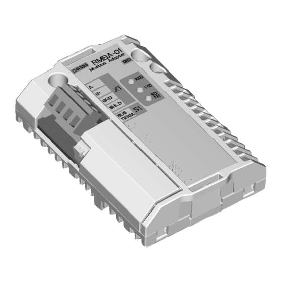
Fixing screw Bus termination switch (S1) (CHASSIS) Terminal block for bus cable connection (X1) Figure 2-1 The construction of the Modbus link and the RMBA-01 Adapter module layout. Delivery check The option package for the RMBA-01 Modbus Adapter module contains: •... -
Page 15: Compatibility
Chapter 2 – Overview Compatibility The RMBA-01 is compatible with ACS 800 Standard Application Program version ASXR7000 or later. Warranty and The warranty for your ABB drive and options covers liability manufacturing defects. The manufacturer carries no information responsibility for damage due to transport or unpacking. - Page 16 Chapter 2 – Overview RMBA-01 User’s manual Phone: 800.894.0412 - Fax: 888.723.4773 - Web: www.clrwtr.com - Email: info@clrwtr.com...
-
Page 17: Chapter 3 - Installation
ACS 800 Hardware Manual. Mounting The RMBA-01 is to be inserted into the position marked SLOT 1 on the drive. The module is held in place with plastic retaining clips and two screws. The screws also... -
Page 18: Wiring
Arrange the bus cables as far away from the motor cables as possible. Avoid parallel runs. Use bushings at cable entries. The terminal block (X1) on the RMBA-01 is of the detachable type for easy connection. The Modbus cable shield may be directly earthed at one node only. -
Page 19: Wiring Diagrams
Termination: ON Figure 3-2 Two-wire connection Modbus RMBA-01 RMBA-01 Master [Station N] [Station 1] Termination: ON Termination: OFF Termination: ON Figure 3-3 Three-wire connection (preferred practice) RMBA-01 User’s manual Phone: 800.894.0412 - Fax: 888.723.4773 - Web: www.clrwtr.com - Email: info@clrwtr.com... -
Page 20: Bus Termination
Chapter 3 – Installation Bus termination The built-in active bus termination must be switched on if the RMBA-01 module is installed at the end of the bus. Otherwise the bus termination must be switched off. Bus termination prevents signal reflections from the bus cable ends. -
Page 21: Chapter 4 - Programming
ABB drives can receive control information from multiple sources including digital inputs, analogue inputs, the drive control panel and a communication module (e.g. RMBA-01). ABB drives allow the user to separately determine the source for each type of control information (Start, Stop, Direction, Reference, Fault Reset, etc.). - Page 22 Chapter 4 – Programming RMBA-01 User’s manual Phone: 800.894.0412 - Fax: 888.723.4773 - Web: www.clrwtr.com - Email: info@clrwtr.com...
-
Page 23: Chapter 5 - Communication
Register addresses 4GGPP are shown in Table Parameter mapping. In this table GG is the group number, and PP is the parameter number within the group. RMBA-01 User’s manual Phone: 800.894.0412 - Fax: 888.723.4773 - Web: www.clrwtr.com - Email: info@clrwtr.com... - Page 24 Modbus interface will return an exception code to the controller. Refer to the drive manuals for its data sets, group and parameter numbers supported. RMBA-01 User’s manual Phone: 800.894.0412 - Fax: 888.723.4773 - Web: www.clrwtr.com - Email: info@clrwtr.com...
-
Page 25: Exception Codes
ILLEGAL DATA VALUE Value is outside min-max limits. Parameter is read-only. Data update The RMBA-01 module has been designed for time- optimised, reliable data transfer between the Modbus network and the drive. Table 5-3 Function codes. Code Name... - Page 26 Chapter 5 – Communication RMBA-01 User’s manual Phone: 800.894.0412 - Fax: 888.723.4773 - Web: www.clrwtr.com - Email: info@clrwtr.com...
-
Page 27: Chapter 6 - Fault Tracing
Verify all the connections on the module. Check that problems • the Modbus cable is connected correctly to terminal block X1. • the RMBA-01 module is correctly connected on the RMIO board using the fixing screws. Drive setup Drive parameters can be read, but control commands (Start/Stop or Reference) do not work. -
Page 28: Diagnostic Leds
Chapter 6 – Fault tracing Diagnostic LEDs There are three diagnostic LEDs on the RMBA-01 module. Two green LEDs show the transmit and receive activity. A yellow LED shows the status of the module. The RxD LED blinks every time a Modbus message is received by the RMBA-01 (independent of the node address setting). -
Page 29: Appendix A - Technical Data
• One 4-pole terminal block for connection of the fieldbus cable, detachable (max 1.5 mm Hardware settings: • One DIP switch for bus termination selection Settings: Via drive interface (control panel) RMBA-01 User’s manual Phone: 800.894.0412 - Fax: 888.723.4773 - Web: www.clrwtr.com - Email: info@clrwtr.com... -
Page 30: Fieldbus Link
• Maximum Bus Length: 1200 m Topology: Multi-drop Serial communication type: Asynchronous, half Duplex Transfer rate: 600, 1200, 2400, 4800, 9600, 19200 bit/s Protocol: Modbus RTU RMBA-01 User’s manual Phone: 800.894.0412 - Fax: 888.723.4773 - Web: www.clrwtr.com - Email: info@clrwtr.com...
Need help?
Do you have a question about the RMBA-01 and is the answer not in the manual?
Questions and answers