Table of Contents
Advertisement
Quick Links
Advertisement
Table of Contents
Troubleshooting

Related Manuals for Honeywell Vuquest 3330


Summary of Contents for Honeywell Vuquest 3330
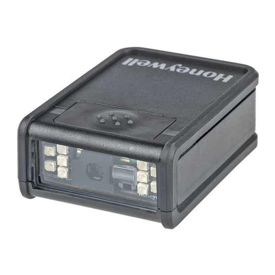
- Page 1 Vuquest™ 3320g Area-Imaging Scanner User Guide...
- Page 2 Disclaimer Honeywell International Inc. (“HII”) reserves the right to make changes in specifications and other information contained in this document without prior notice, and the reader should in all cases consult HII to determine whether any such changes have been made. The information in this publication does not represent a commitment on the part of HII.
-
Page 3: Table Of Contents
TABLE OF CONTENTS Customer Support ........................xiii Technical Assistance ......................xiii Product Service and Repair ....................xiii Limited Warranty ........................xiii Send Feedback ........................xiii Chapter 1 - Getting Started................1 About This Manual......................... 1 Unpacking Your Device........................ 1 Connecting the Device......................... 1 Connecting with USB ...................... - Page 4 ® Verifone Ruby Terminal Default Settings..............11 ® Gilbarco Terminal Default Settings ................11 Honeywell Bioptic Aux Port Configuration ..............12 © Datalogic™ Magellan Aux Port Configuration ............12 NCR Bioptic Aux Port Configuration ................12 Wincor Nixdorf Terminal Default Settings ..............13 Wincor Nixdorf Beetle™ Terminal Default Settings..........13 Keyboard Country Layout......................14...
- Page 5 Trigger Click............................34 Good Read and Error Indicators.....................34 Beeper – Good Read ......................34 Beeper Volume – Good Read ....................34 Beeper Pitch – Good Read ....................35 Beeper Pitch – Error ......................35 Beeper Duration – Good Read..................36 LED – Good Read........................36 Number of Beeps – Good Read..................36 Number of Beeps –...
- Page 6 User-Specified Reread Delay ....................46 2D Reread Delay...........................47 Illumination Lights........................47 Aimer Delay ............................48 User-Specified Aimer Delay ....................48 Aimer Mode ............................48 Centering ............................49 Preferred Symbology........................50 High Priority Symbology ....................51 Low Priority Symbology ......................51 Preferred Symbology Time-out..................52 Preferred Symbology Default ...................52 Output Sequence Overview .....................52 Output Sequence Editor.....................52 To Add an Output Sequence .....................52 Other Programming Selections..................53...
- Page 7 Prefix Selections ...........................62 Suffix Selections...........................62 Function Code Transmit ......................62 Intercharacter, Interfunction, and Intermessage Delays .........................63 Intercharacter Delay......................63 User Specified Intercharacter Delay ................63 Interfunction Delay.......................64 Intermessage Delay ......................64 Chapter 5 - Data Formatting.................65 Data Format Editor Introduction ...................65 Add a Data Format........................66 Other Programming Selections ..................67 Terminal ID Table..........................68 Data Format Editor Commands .....................68...
- Page 8 External Illumination Schematic ..................90 Chapter 7 - Symbologies................91 All Symbologies ..........................92 Message Length Description....................92 Codabar ............................93 Codabar On/Off........................93 Codabar Start /Stop Characters ..................93 Codabar Check Character....................93 Codabar Concatenation .....................94 Codabar Message Length ....................95 Code 39............................95 Code 39 On/Off ........................95 Code 39 Start /Stop Characters..................95 Code 39 Check Character ....................96 Code 39 Message Length ....................96...
- Page 9 Straight 2 of 5 Industrial On/Off..................104 Straight 2 of 5 Industrial Message Length ..............104 Straight 2 of 5 IATA (two-bar start/stop) .................105 Straight 2 of 5 IATA On/Off.....................105 Straight 2 of 5 IATA Message Length .................105 Matrix 2 of 5 ..........................106 Matrix 2 of 5 On/Off ......................106 Matrix 2 of 5 Message Length..................106 Code 11 ............................107...
- Page 10 Coupon GS1 DataBar Output ....................115 UPC-E0 ............................115 UPC-E0 On/Off........................115 UPC-E0 Expand........................115 UPC-E0 Addenda Required.................... 116 UPC-E0 Addenda Separator ..................116 UPC-E0 Check Digit......................116 UPC-E0 Leading Zero....................... 117 UPC-E0 Addenda ....................... 117 UPC-E1 ............................117 EAN/JAN-13 ..........................118 EAN/JAN-13 On/Off ......................
- Page 11 GS1 DataBar Expanded Message Length ..............126 Trioptic Code ..........................126 Codablock A..........................127 Codablock A On/Off ......................127 Codablock A Message Length..................127 Codablock F..........................128 Codablock F On/Off ......................128 Codablock F Message Length..................128 PDF417 ............................129 PDF417 On/Off........................129 PDF417 Message Length ....................129 MacroPDF417 ..........................129 MicroPDF417 ..........................130 MicroPDF417 On/Off .......................130 MicroPDF417 Message Length..................130 GS1 Composite Codes ......................130...
- Page 12 Aztec Code On/Off......................137 Aztec Code Message Length ..................137 Aztec Append ........................137 Aztec Code Page ......................... 138 Chinese Sensible (Han Xin) Code ..................138 Han Xin Code On/Off ....................... 138 Han Xin Code Message Length ..................138 Postal Codes - 2D ........................139 Single 2D Postal Codes:....................
- Page 13 Show Software Revision ......................166 Show Data Format ........................166 Test Menu.............................166 TotalFreedom..........................166 Application Plug-Ins (Apps)....................167 EZConfig Cloud for Scanning Introduction..............167 EZConfig Cloud for Scanning Operations ..............167 Install EZConfig Cloud for Scanning.................168 Resetting the Factory Defaults....................169 Chapter 10 - Serial Programming Commands........171 Conventions ..........................171 Menu Command Syntax......................171 Query Commands ........................172...
- Page 14 Guaranteed Performance ....................199 Mounting General Guidelines ..................... 200 Standard Cable Pinouts ......................201 Keyboard Wedge......................... 201 Serial Output ........................202 USB ............................202 Scanner ..........................203 Chapter 12 - Maintenance and Troubleshooting ........205 Repairs ............................205 Maintenance..........................205 Cleaning the Scanner ....................... 205 Cleaning the Window......................
-
Page 15: Customer Support
For our latest contact information, see www.honeywellaidc.com/locations. Product Service and Repair Honeywell International Inc. provides service for all of its products through service centers throughout the world. To find your service center, go to www.honey- wellaidc.com... - Page 16 Vuquest 3320g User Guide...
-
Page 17: Chapter 1 - Getting Started
Vuquest™ 3320 area-imaging scanner. Product specifications, dimensions, war- ranty, and customer support information are also included. Honeywell bar code scanners are factory programmed for the most common ter- minal and communications settings. If you need to change these settings, pro- gramming is accomplished by scanning the bar codes in this guide. -
Page 18: Connecting With Keyboard Wedge
1. Connect the appropriate interface cable to the device first, then to the com- puter. Scanner USB Connection: b. The scanner beeps. c. Verify the scanner operation by scanning a bar code from the Sample Symbols in the back of this manual. The unit defaults to a USB PC Keyboard. -
Page 19: Connecting With Rs232 Serial Port
Turn off power and disconnect the keyboard cable from the back of the ter- minal/computer. b. Connect the appropriate interface cable to the device and to the terminal/ computer. Scanner Keyboard Wedge Connection: c. Turn the terminal/computer power back on. The scanner beeps. d. -
Page 20: Reading Techniques
c. Plug the serial connector into the serial port on your computer. Tighten the two screws to secure the connector to the port. d. Once the scanner has been fully connected, power up the computer. This interface programs 115,200 baud, 8 data bits, no parity, and 1 stop bit. Note: Please note, the end of the cable with the ferrite plugs into the scanner. -
Page 21: Menu Bar Code Security Settings
Menu Bar Code Security Settings Honeywell scanners are programmed by scanning menu bar codes or by sending serial commands to the scanner. If you want to restrict the ability to scan menu codes, you can use the Menu Bar Code Security settings. Please contact the nearest... - Page 22 Vuquest 3320g User Guide...
-
Page 23: Chapter 2 - Programming The Interface
CHAPTER PROGRAMMING THE INTERFACE Introduction This chapter describes how to program your system for the desired interface. Programming the Interface - Plug and Play Plug and Play bar codes provide instant scanner set up for commonly used inter- faces. Note: After you scan one of the codes, power cycle the host terminal to have the interface in effect. -
Page 24: Laptop Direct Connect
Laptop Direct Connect For most laptops, scanning the Laptop Direct Connect bar code allows operation of the scanner in parallel with the integral keyboard. The following Laptop Direct Con- nect bar code also programs a carriage return (CR) suffix and turns on Emulate External Keyboard (page 22). -
Page 25: Usb Pc Or Macintosh Keyboard
Each bar code above also programs the following suffixes for each symbology: Symbology Suffix Symbology Suffix EAN 8 Code 39 00 0A 0B EAN 13 Interleaved 2 of 5 00 0D 0B UPC A Code 128 00 18 0B UPC E Code 39 00 0A 0B USB PC or Macintosh Keyboard... -
Page 26: Usb Serial
Scan the following code to program the scanner to emulate a regular RS232-based COM Port. If you are using a Microsoft® Windows® PC, you will need to download a driver from the Honeywell website (www.honeywellaidc.com). The driver will use the next available COM Port number. Apple® Macintosh computers recognize the scanner as a USB CDC class device and automatically use a class driver. -
Page 27: Verifone ® Ruby Terminal Default Settings
* ReM On ® Verifone Ruby Terminal Default Settings Scan the following Plug and Play code to program the scanner for a Verifone Ruby terminal. This bar code sets the baud rate to 1200 bps and the data format to 8 data bits, Mark parity bit, 1 stop bit. -
Page 28: Honeywell Bioptic Aux Port Configuration
Honeywell Bioptic Aux Port Configuration Scan the following Plug and Play code to program the scanner for a Honeywell bioptic scanner auxiliary port configuration. This bar code sets the baud rate to 38400 bps and the data format to 8 data bits, no parity, 1 stop bit. -
Page 29: Wincor Nixdorf Terminal Default Settings
NCR Bioptic Settings Note: If you are having unexpected results with this programming code, scan the Activate Defaults bar code on page 5 first, then scan the programming code above. Wincor Nixdorf Terminal Default Settings Scan the following Plug and Play code to program the scanner for a Wincor Nixdorf terminal. -
Page 30: Keyboard Country Layout
Keyboard Country Layout SIf your interface is USB Keyboard or Keyboard Wedge, your keyboard layout default is a US keyboard. To change this layout, refer to the chart below for your keyboard country. Scan the appropriate bar code below to change the layout. By default, national character replacements are used for the following characters: #$@[\]^‘{|}~ See Symbology Charts... - Page 31 Keyboard Countries (Continued) Bulgaria (Cyrillic) Bulgaria (Latin) Canada (French legacy) Canada (French) Canada (Multilingual) Croatia Czech Czech (Programmers) Czech (QWERTY) Czech (QWERTZ) Denmark Dutch (Netherlands) Vuquest 3320g User Guide...
- Page 32 Keyboard Countries (Continued) Estonia Faroese Finland France Gaelic Germany Greek Greek (220 Latin) Greek (220) Greek (319 Latin) Greek (319) Greek (Latin) Vuquest 3320g User Guide...
- Page 33 Keyboard Countries (Continued) Greek (MS) Greek (Polytonic) Hebrew Hungarian (101 key) Hungary Iceland Irish Italian (142) Italy Japan ASCII Kazakh Kyrgyz (Cyrillic) Vuquest 3320g User Guide...
- Page 34 Keyboard Countries (Continued) Latin America Latvia Latvia (QWERTY) Lithuania Lithuania (IBM) Macedonia Malta Mongolian (Cyrillic) Norway Poland Polish (214) Polish (Programmers) Vuquest 3320g User Guide...
- Page 35 Keyboard Countries (Continued) Portugal Romania Russia Russian (MS) Russian (Typewriter) Serbia (Cyrillic) Serbia (Latin) Slovakia Slovakia (QWERTY) Slovakia (QWERTZ) Slovenia Vuquest 3320g User Guide...
- Page 36 Keyboard Countries (Continued) Spain Spanish variation Sweden Switzerland (French) Switzerland (German) Tatar Turkey F Turkey Q Ukrainian United Kingdom United States (Dvorak) United States (Dvorak left) Vuquest 3320g User Guide...
-
Page 37: Keyboard Style
Keyboard Countries (Continued) United Stated (Dvorak United States (International) Uzbek (Cyrillic) Keyboard Style This programs keyboard styles, such as Caps Lock and Shift Lock. If you have used Keyboard Conversion settings, they will override any of the following Keyboard Style settings. -
Page 38: Keyboard Conversion
Autocaps via NumLock bar code should be scanned in countries (e.g., Germany, France) where the Caps Lock key cannot be used to toggle Caps Lock. The Num- Lock option works similarly to the regular Autocaps, but uses the NumLock key to retrieve the current state of the Caps Lock. -
Page 39: Control Character Output
Control Character Output This selection sends a text string instead of a control character. For example, when the control character for a carriage return is expected, the output would display [CR] instead of the ASCII code of 0D. Refer to ASCII Conversion Chart (Code Page 1252) on page 212. - Page 40 DOS Mode Control + X Mode On Windows Mode Prefix/Suffix Turbo Mode The scanner sends characters to a terminal faster. If the terminal drops characters, do not use Turbo Mode. Default = Off Turbo Mode On * Turbo Mode Off Numeric Keypad Mode Sends numeric characters as if entered from a numeric keypad.
-
Page 41: Rs232 Modifiers
RS232 Modifiers RS232 Baud Rate Baud Rate sends the data from the scanner to the terminal at the specified rate. The host terminal must be set for the same baud rate as the scanner. Default = 115,200. 1200 2400 4800 9600 19200 38400... -
Page 42: Rs232 Word Length: Data Bits, Stop Bits, And Parity
1200 2400 4800 9600 19200 38400 57,600 * 115,200 RS232 Word Length: Data Bits, Stop Bits, and Parity Data Bits sets the word length at 7 or 8 bits of data per character. If an application requires only ASCII Hex characters 0 through 7F decimal (text, digits, and punctua- tion), select 7 data bits. - Page 43 Stop Bits sets the stop bits at 1 or 2. Default = 1. Parity provides a means of checking character bit patterns for validity. Default = None. 7 Data, 1 Stop, Parity Even 7 Data, 1 Stop, Parity None 7 Data, 1 Stop, Parity Odd 7 Data, 2 Stop, Parity Even 7 Data, 2 Stop Parity None 7 Data, 2 Stop, Parity Odd...
-
Page 44: Rs232 Receiver Time-Out
RS232 Receiver Time-Out The unit stays awake to receive data until the RS232 Receiver Time-Out expires. A manual or serial trigger resets the time-out. When an RS232 receiver is sleeping, a character may be sent to wake up the receiver and reset the time-out. A transac- tion on the CTS line will also wake up the receiver. -
Page 45: Rs232 Timeout
RS232 Timeout When using Flow Control with Timeout, you must program the length of the delay you want to wait for CTS from the host. Set the length (in milliseconds) for a time- out by scanning the bar code below, then setting the timeout (from 1-5100 milli- seconds) by scanning digits from the inside back cover, then scanning Save. -
Page 46: Scanner To Bioptic Communication
Scanner to Bioptic Communication The following settings are used to set up communication between Honeywell scan- ners and bioptic scanners. Note: The scanner’s baud rate must be set to 38400 and the RS232 timeout must be set to 3000 in order to communicate with a bioptic scanner. See "RS232 Modifiers" on page... -
Page 47: Scanner-Bioptic Ack/Nak Timeout
Scanner-Bioptic ACK/NAK Timeout This allows you to set the length (in milliseconds) for a timeout for a bioptic scan- ner’s ACK/NAK response. Scan the bar code below, then set the timeout (from 1- 30,000 milliseconds) by scanning digits from the inside back cover, then scanning Save. - Page 48 Vuquest 3320g User Guide...
-
Page 49: Chapter 3 - Input/Output Settings
CHAPTER INPUT/OUTPUT SETTINGS Power Up Beeper The scanner can be programmed to beep when it’s powered up. Scan the Off bar code(s) if you don’t want a power up beep. Default = Power Up Beeper On - Scanner. Power Up Beeper Off - Scanner * Power Up Beeper On - Scanner... -
Page 50: Trigger Click
Trigger Click To hear an audible click every time the scanner button is pushed, scan the Trigger Click On bar code below. Scan the Trigger Click Off code if you don’t wish to hear the click. (This feature has no effect on serial or automatic triggering.) Default = Trigger Click Off. -
Page 51: Beeper Pitch - Good Read
* High Beeper Pitch – Good Read The beeper pitch codes modify the pitch (frequency) of the beep the scanner emits on a good read. Default = Medium. Low (1600 Hz) * Medium (2700 Hz) High (4200 Hz) Beeper Pitch – Error The beeper pitch codes modify the pitch (frequency) of the sound the scanner emits when there is a bad read or error. -
Page 52: Beeper Duration - Good Read
Beeper Duration – Good Read The beeper duration codes modify the length of the beep the scanner emits on a good read. Default = Normal. * Normal Beep Short Beep Short Beep LED – Good Read The LED indicator can be programmed On or Off in response to a good read. Default = On. -
Page 53: Good Read Delay
to an error. To change the number of error beeps, scan the bar code below and then scan a digit (1-9) bar code and the Save bar code on the inside the back cover of this manual. Default = 1. Number of Error Beeps/LED Flashes Good Read Delay This sets the minimum amount of time before the scanner can read another bar... -
Page 54: Led Illumination - Manual Trigger
range than Normal mode. Enhanced mode is best used when you require a very fast scan speed and don’t require a long working range. Default = Manual Trigger- Normal. * Manual Trigger - Normal Manual Trigger - LED Illumination - Manual Trigger If you wish to set the illumination LED brightness, scan one of the bar codes below. -
Page 55: Presentation Mode
command. After scanning the Read Time-Out bar code, set the time-out duration (from 0-300,000 milliseconds) by scanning digits on the inside the back cover, then scanning Save. Default = 30,000 ms. Read Time-Out Presentation Mode Presentation Mode uses ambient light and scanner illumination to detect bar codes. -
Page 56: Presentation Led Behavior After Decode
Presentation LED Behavior after Decode When a scanner is in presentation mode, the LEDs dim 30 seconds after a bar code is decoded. If you wish to dim the LEDs immediately after a bar code is decoded, scan the LEDs Off bar code, below. Default = LEDs On. * LEDs On LEDs Off Presentation Sensitivity... - Page 57 In the example below, the white box is the centering window. The centering window has been set to 20% left, 30% right, 8% top, and 25% bottom. Since Bar Code 1 passes through the centering window, it will be read. Bar Code 2 does not pass through the centering window, so it will not be read.
-
Page 58: Codegate
Bottom of Presentation Centering Window Left of Presentation Centering Window Right of Presentation Centering Window ® CodeGate When CodeGate is On, the button is used to allow decoded data to be transmitted to the host system. The scanner remains on, scanning and decoding bar codes, but the bar code data is not transmitted until the button is pushed. -
Page 59: Mobile Phone Read Mode
Streaming Presentation Mode - Enhanced When using Preferred Symbology (page 3-50), a lower priority symbol must be centered on the aiming pattern to be read in Streaming Presentation Mode. Mobile Phone Read Mode When this mode is selected, your scanner is optimized to read bar codes from mobile phone or other LED displays. -
Page 60: Character Activation Mode
Character Activation Mode You may use a character sent from the host to trigger the scanner to begin scan- ning. When the activation character is received, the scanner continues scanning until either the Character Activation Laser Timeout (page 3-44), the deactivation character is received (see Deactivation Character on page 46), or a bar code is... -
Page 61: Character Deactivation Mode
Character Deactivation Mode If you have sent a character from the host to trigger the scanner to begin scanning, you can also send a deactivation character to stop scanning. Scan the following On bar code to use character deactivation, then use Deactivation Character (fol- lowing) to select the character you will send from the host to terminate scanning. -
Page 62: Deactivation Character
Deactivation Character This sets the character used to terminate scanning when using Character Deacti- vation Mode. On the ASCII Conversion Chart (Code Page 1252), page 212, find the hex value that represents the character you want to use to terminate scanning. Scan the following bar code, then use the Programming Chart to read the alphanu-... -
Page 63: 2D Reread Delay
2D Reread Delay Sometimes 2D bar codes can take longer to read than other bar codes. If you wish to set a separate Reread Delay for 2D bar codes, scan one of the programming codes that follows. 2D Reread Delay Off indicates that the time set for Reread Delay is used for both 1D and 2D bar codes. -
Page 64: Aimer Delay
Aimer Delay The aimer delay allows a delay time for the operator to aim the scanner before the picture is taken. Use these codes to set the time between when the button is pushed and when the picture is taken. During the delay time, the aiming light will appear, but the LEDs won’t turn on until the delay time is over. -
Page 65: Centering
Centering Use Centering to narrow the scanner’s field of view to make sure that when the scanner is hand-held, it reads only those bar codes intended by the user. For instance, if multiple codes are placed closely together, centering will insure that only the desired codes are read. -
Page 66: Preferred Symbology
Scan Centering On, then scan one of the following bar codes to change the top, bottom, left, or right of the centering window. Then scan the percent you want to shift the centering window using digits on the inside back cover of this manual. Scan Save. -
Page 67: High Priority Symbology
If the time-out period expires before a high priority symbology is read, the scanner will read any bar code in its view (low priority or unspecified). If there is no bar code in the scanner’s view after the time-out period expires, then no data is reported. Note: A low priority symbol must be centered on the aiming pattern to be read. -
Page 68: Preferred Symbology Time-Out
Preferred Symbology Time-out Once you have enabled Preferred Symbology and entered the high and low priority symbologies, you must set the time-out period. This is the period of time the scan- ner will search for a high priority bar code after a low priority bar code has been encountered. -
Page 69: Other Programming Selections
3. Length Specify what length (up to 9999 characters) of data output will be acceptable for this symbology. Scan the four digit data length Programming Chart, beginning on page 341. (Note: 50 characters is entered as 0050. 9999 is a universal number, indicating all lengths.) When calculating the length, you must count any programmed prefixes, suffixes, or formatted characters as part of the length (unless using 9999). - Page 70 start character match for Code 39, 41h = “A” termination string for first code code identifier for Code 128 9999 code length that must match for Code 128, 9999 = all lengths start character match for Code 128, 42h = “B” termination string for second code code identifier for Code 93 9999...
-
Page 71: Output Sequence Editor
Output Sequence Editor Enter Sequence Default Sequence Partial Sequence If an output sequence operation is terminated before all your output sequence cri- teria are met, the bar code data acquired to that point is a “partial sequence.” Scan Discard Partial Sequence to discard partial sequences when the output sequence operation is terminated before completion. -
Page 72: Multiple Symbols
On/Not Required *Off Multiple Symbols When this programming selection is turned On, it allows you to read multiple sym- bols with a single push of the scanner’s button. If you push and hold the button, aiming the scanner at a series of symbols, it reads unique symbols once, beeping (if turned on) for each read. -
Page 73: Video Reverse
Video Reverse Video Reverse is used to allow the scanner to read bar codes that are inverted. The Video Reverse Off bar code below is an example of this type of bar code. Scan Video Reverse Only to read only inverted bar codes. Scan Video Reverse and Stan- dard Bar Codes to read both types of codes. -
Page 74: Working Orientation
Working Orientation Some bar codes are direction-sensitive. For example, KIX codes and OCR can mis- read when scanned sideways or upside down. Use the working orientation settings if your direction-sensitive codes will not usually be presented upright to the scan- ner. -
Page 75: Chapter 4 - Data Editing
CHAPTER DATA EDITING Prefix/Suffix Overview When a bar code is scanned, additional information is sent to the host computer along with the bar code data. This group of bar code data and additional, user-defined data is called a “message string.” The selections in this section are used to build the user-defined data into the message string. -
Page 76: To Add A Prefix Or Suffix
• When setting up for specific symbologies (as opposed to all symbologies), the specific symbology ID value counts as an added prefix or suffix character. • The maximum size of a prefix or suffix configuration is 200 characters, which includes header information. To Add a Prefix or Suffix: Step 1. -
Page 77: To Add A Carriage Return Suffix To All Symbologies
Step 1. Scan the Clear One Prefix or Clear One Suffix symbol. Step 2. Determine the 2 digit Hex value from the Symbology Chart (included in Symbology Charts beginning on page 209) for the symbology from which you want to clear the prefix or suffix. Step 3. -
Page 78: Prefix Selections
Prefix Selections Add Prefix Clear One Prefix Clear All Prefixes Suffix Selections Add Suffix Clear One Suffix Clear All Suffixes Function Code Transmit When this selection is enabled and function codes are contained within the scanned data, the scanner transmits the function code to the terminal. Charts of these function codes are provided in ASCII Conversion Chart (Code Page 1252) starting on... -
Page 79: Intercharacter, Interfunction, And Intermessage Delays
Intercharacter, Interfunction, and Intermessage Delays Some terminals drop information (characters) if data comes through too quickly. Intercharacter, interfunction, and intermessage delays slow the transmission of data, increasing data integrity. Intercharacter Delay An intercharacter delay of up to 5000 milliseconds (in 5ms increments) may be placed between the transmission of each character of scanned data. -
Page 80: Interfunction Delay
To remove this delay, scan the Delay Length bar code, and set the number of delays to 0. Scan the Save bar code using the inside the back cover of this manual. Interfunction Delay An interfunction delay of up to 5000 milliseconds (in 5ms increments) may be placed between the transmission of each control character in the message string. -
Page 81: Chapter 5 - Data Formatting
CHAPTER DATA FORMATTING Data Format Editor Introduction You may use the Data Format Editor to change the scanner’s output. For example, you can use the Data Format Editor to insert characters at certain points in bar code data as it is scanned. The selections in the following pages are used only if you wish to alter the output. -
Page 82: Add A Data Format
If you have changed data format settings, and wish to clear all formats and return to the factory defaults, scan the Default Data Format code below. * Default Data Format Add a Data Format Step 1. Scan the Enter Data Format symbol (page 67). -
Page 83: Other Programming Selections
Step 7. Scan Save to save your data format, or Discard to exit without saving your changes.. Enter Data Format Save Discard Other Programming Selections • Clear One Data Format This deletes one data format for one symbology. If you are clearing the primary format, scan 0 from the Programming Chart, beginning on page 341. -
Page 84: Terminal Id Table
Terminal ID Table Terminal Terminal Model(s) PC keyboard (HID) Mac Keyboard PC Keyboard (Japanese) Serial (COM driver required) HID POS USB SurePOS Handheld USB SurePOS Tabletop Serial RS232 TTL RS232 True RS485 (IBM-HHBCR 1+2, 46xx) Keyboard PS2 compatibles AT compatibles Data Format Editor Commands When working with the Data Format Editor, a virtual cursor is moved along your input data string. - Page 85 F2 Example: Send a number of characters Send the first 10 characters from the bar code above, followed by a carriage return. Command string: F2100D F2 is the “Send a number of characters” command 10 is the number of characters to send 0D is the hex value for a CR The data is output as: 1234567890 F2 and F1 Example: Split characters into 2 lines...
- Page 86 Using the bar code above, send all characters up to but not including “D,” followed by a carriage return. Command string: F3440D F3 is the “Send all characters up to a particular character” command 44 is the hex value for a 'D” 0D is the hex value for a CR The data is output as: 1234567890ABC...
- Page 87 Insert a character multiple times F4 Send “xx” character “nn” times in the output message, leaving the cursor in the current position. Syntax = F4xxnn where xx stands for the insert character’s hex value for its ASCII code, and nn is the numeric value (00-99) for the number of times it should be sent.
- Page 88 1234567890**ABCDEFGHIJ <CR> Insert symbology name B3 Insert the name of the bar code’s symbology in the output message, without moving the cursor. Only symbologies with a Honeywell ID are included (see Symbology Charts on page 327). Refer to the ASCII Conversion Chart (Code Page 1252), beginning on page 330 for decimal, hex and character codes.
-
Page 89: Move Commands
0D is the hex value for a CR The data is output as: Code128 20 1234567890ABCDEFGHIJ <CR> Insert key strokes B5 Insert a key stroke or combination of key strokes. Key strokes are dependent on your keyboard (see Keyboard Key References on page 337). - Page 90 Move the cursor forward 3 characters, then send the rest of the bar code data from the bar code above. End with a carriage return. Command string: F503F10D F5 is the “Move the cursor forward a number of characters” command 03 is the number of characters to move the cursor F1 is the “Send all characters”...
-
Page 91: Search Commands
Move the cursor to the end EA Move the cursor to the last character in the input message. Syntax = EA. Search Commands Search forward for a character F8 Search the input message forward for “xx” character from the current cursor position, leaving the cursor pointing to the “xx”... - Page 92 Search forward for a string B0 Search forward for “s” string from the current cursor position, leaving cursor pointing to “s” string. Syntax = B0nnnnS where nnnn is the string length (up to 9999), and S consists of the ASCII hex value of each character in the match string. For example, B0000454657374 will search forward for the first occurrence of the 4 character string “Test.”...
-
Page 93: Miscellaneous Commands
Search forward for a non-matching character E6 Search the input message forward for the first non-“xx” character from the current cursor position, leaving the cursor pointing to the non-“xx” character. Syntax = E6xx where xx stands for the search character’s hex value for its ASCII code. Refer to the ASCII Conversion Chart (Code Page 1252), beginning on page 330 for decimal, hex and character codes. - Page 94 FB Example: Remove spaces in bar code data This example shows a bar code that has spaces in the data. You may want to remove the spaces before sending the data. Using the bar code above: Command string: FB0120F10D FB is the “Suppress characters” command 01 is the number of character types to be suppressed 20 is the hex value for a space F1 is the “Send all characters”...
- Page 95 0D is the hex value for a CR (the character that will replace the 0) F1 is the “Send all characters” command 0D is the hex value for a CR The data is output as: 1234 5678 <CR> Stop replacing characters E5 Terminates character replacement.
- Page 96 If this bar code is read, the next data format, if there is one, will be used on the data. If there is no other format, the format fails and the raw data is output as AB1234. If this bar code is read: the data is output as: 1234AB <CR>...
-
Page 97: Data Formatter
Discard Data B8 Discards types of data. For example, you may want to discard Code 128 bar codes that begin with the letter A. In step 4 (page 66), select 6A (for Code 128), and in step 5, select 9999 (for all lengths). Enter FE41B8 to compare and discard Code 128 bar codes that begin with the letter A. -
Page 98: Data Format Non-Match Error Tone
found for a particular symbol, those prefixes and suffixes are not transmitted. Any data that does not match your data format requirements generates an error tone. If you wish to process this type of bar code without generating an error tone, see Data Format Non-Match Error Tone. -
Page 99: Primary/Alternate Data Formats
Primary/Alternate Data Formats You can save up to four data formats, and switch between these formats. Your pri- mary data format is saved under 0. Your other three formats are saved under 1, 2, and 3. To set your device to use one of these formats, scan one of the bar codes below. - Page 100 Single Scan-Data Format 3 Vuquest 3320g User Guide...
-
Page 101: Chapter 6 - External Input / Output
CHAPTER EXTERNAL INPUT / OUTPUT The Vuquest 3320 scanner can be integrated with a variety of third party devices. The External Trigger and Illumination Controls can be configured using the bar codes in this chapter. These controls offer simple trigger signals. An External I/O license and cable are required;... -
Page 102: External Trigger Polarity
External Trigger Polarity External Trigger Polarity has two states, High and Low. A digital high polarity is 1 and a digital low polarity is 0. If the third party device triggers on low polarity, 0, scan the External Trigger Polarity Low bar code. Default = External Trigger Polarity High. -
Page 103: External Trigger Parameters
External Trigger Parameters Absolute Maximum Low Value: -0.5 Volts The input is protected by an input protection diode High Value: +5.5 Volts on the ground side. Maximum Input Voltage The input voltage can be below ground provided it is current limited below the value shown on the next line of this table. -
Page 104: External Trigger Schematic
External Trigger Schematic External Output External Illumination Control The External Illumination Control allows the third party device to use external illu- mination, supplemental to the illumination from the scanner. If the illumination will be provided by the third party device, scan the External Illumination Control On bar code. -
Page 105: External Illumination Parameters
External Illumination Control External Illumination Parameters Absolute Maximum High Value: 6 Volts This allows a pull-up to be connected to this line Maximum voltage on output pin with scanner powered provided it does not exceed the current on the down. next line of this table while operating. -
Page 106: External Illumination Schematic
External Illumination Schematic Vuquest 3320g User Guide... -
Page 107: Chapter 7 - Symbologies
CHAPTER SYMBOLOGIES This programming section contains the following menu selections. Refer to Chapter 10 for settings and defaults. • All Symbologies • Interleaved 2 of 5 • Aztec Code • Korea Post • China Post (Hong Kong 2 of 5) •... -
Page 108: All Symbologies
All Symbologies If you want to decode all the symbologies allowable for your scanner, scan the All Symbologies On code. If on the other hand, you want to decode only a particular symbology, scan All Symbologies Off followed by the On symbol for that particular symbology. -
Page 109: Codabar
Codabar <Default All Codabar Settings> Codabar On/Off * On Codabar Start /Stop Characters Start/Stop characters identify the leading and trailing ends of the bar code. You may either transmit, or not transmit Start/Stop characters. Default = Don’t Trans- mit. Transmit * Don’t Transmit Codabar Check Character Codabar check characters are created using different “modulos.”... -
Page 110: Codabar Concatenation
When Check Character is set to Validate, but Don’t Transmit, the unit will only read Codabar bar codes printed with a check character, but will not transmit the check character with the scanned data. * No Check Character Validate Modulo 16, but Don’t Transmit Validate Modulo 16 and Transmit... -
Page 111: Codabar Message Length
Codabar Message Length Scan the bar codes below to change the message length. Refer to Message Length Description (page 92) for additional information. Minimum and Maximum lengths = 2-60. Minimum Default = 4, Maximum Default = 60. Minimum Message Length Maximum Message Length Code 39 <... -
Page 112: Code 39 Check Character
Code 39 Check Character No Check Character indicates that the scanner reads and transmits bar code data with or without a check character. When Check Character is set to Validate, but Don’t Transmit, the unit only reads Code 39 bar codes printed with a check character, but will not transmit the check character with the scanned data. -
Page 113: Code 32 Pharmaceutical (Paraf)
Code 39 bar codes until it reads a Code 39 bar code that does not have the append trigger. The data is then transmitted in the order in which the bar codes were read (FIFO). Default = Off. * Off Code 32 Pharmaceutical (PARAF) Code 32 Pharmaceutical is a form of the Code 39 symbology used by Italian phar- macies. -
Page 114: Full Ascii
Full ASCII If Full ASCII Code 39 decoding is enabled, certain character pairs within the bar code symbol will be interpreted as a single character. For example: $V will be decoded as the ASCII character SYN, and /C will be decoded as the ASCII character #. -
Page 115: Code 39 Code Page
Code 39 Code Page Code pages define the mapping of character codes to characters. If the data received does not display with the proper characters, it may be because the bar code being scanned was created using a code page that is different from the one the host program is expecting. -
Page 116: Interleaved 2 Of 5 Message Length
When Check Digit is set to Validate and Transmit, the scanner only reads Inter- leaved 2 of 5 bar codes printed with a check digit, and will transmit this digit at the end of the scanned data. Default = No Check Digit. * No Check Digit Validate, but Don’t Transmit Validate and Transmit... -
Page 117: Nec 2 Of 5
NEC 2 of 5 < Default All NEC 2 of 5 Settings > NEC 2 of 5 On/Off * On Check Digit No Check Digit indicates that the scanner reads and transmits bar code data with or without a check digit. When Check Digit is set to Validate, but Don’t Transmit, the unit only reads NEC 2 of 5 bar codes printed with a check digit, but will not transmit the check digit with the scanned data. -
Page 118: Nec 2 Of 5 Message Length
NEC 2 of 5 Message Length Scan the bar codes below to change the message length. Refer to Message Length Description (page 92) for additional information. Minimum and Maximum lengths = 2-80. Minimum Default = 4, Maximum Default = 80. Minimum Message Length Maximum Message Length Code 93... -
Page 119: Code 93 Append
Code 93 Append This function allows the scanner to append the data from several Code 93 bar codes together before transmitting them to the host computer. When this function is enabled, the scanner stores those Code 93 bar codes that start with a space (excluding the start and stop symbols), and does not immediately transmit the data. -
Page 120: Straight 2 Of 5 Industrial (Three-Bar Start/Stop)
Straight 2 of 5 Industrial (three-bar start/stop) <Default All Straight 2 of 5 Industrial Settings> Straight 2 of 5 Industrial On/Off * Off Straight 2 of 5 Industrial Message Length Scan the bar codes below to change the message length. Refer to Message Length Description (page 92) for additional information. -
Page 121: Straight 2 Of 5 Iata (Two-Bar Start/Stop)
Straight 2 of 5 IATA (two-bar start/stop) <Default All Straight 2 of 5 IATA Settings> Straight 2 of 5 IATA On/Off * Off Straight 2 of 5 IATA Message Length Scan the bar codes below to change the message length. Refer to Message Length Description (page 92) for additional information. -
Page 122: Matrix 2 Of 5
Matrix 2 of 5 <Default All Matrix 2 of 5 Settings> Matrix 2 of 5 On/Off * Off Matrix 2 of 5 Message Length Scan the bar codes below to change the message length. Refer to Message Length Description (page 92) for additional information. Minimum and Maximum lengths = 1-80. -
Page 123: Code 11
Code 11 <Default All Code 11 Settings> Code 11 On/Off * Off Check Digits Required This option sets whether 1 or 2 check digits are required with Code 11 bar codes. Default = Two Check Digits. One Check Digit * Two Check Digits Code 11 Message Length Scan the bar codes below to change the message length. -
Page 124: Code 128
Code 128 <Default All Code 128 Settings> Code 128 On/Off * On ISBT 128 Concatenation In 1994 the International Society of Blood Transfusion (ISBT) ratified a standard for communicating critical blood information in a uniform manner. The use of ISBT formats requires a paid license. -
Page 125: Code 128 Append
Maximum Message Length Code 128 Append This function allows the scanner to append the data from several Code 128 bar codes together before transmitting them to the host computer. When the scanner encounters a Code 128 bar code with the append trigger character(s), it buffers Code 128 bar codes until it reads a Code 128 bar code that does not have the append trigger. -
Page 126: Gs1-128
GS1-128 <Default All GS1-128 Settings> GS1-128 On/Off * On GS1-128 Message Length Scan the bar codes below to change the message length. Refer to Message Length Description (page 92) for additional information. Minimum and Maximum lengths = 1-80. Minimum Default = 1, Maximum Default = 80. Minimum Message Length Maximum Message Length Vuquest 3320g User Guide... -
Page 127: Telepen
Telepen <Default All Telepen Settings> Telepen On/Off * Off Telepen Output Using AIM Telepen Output, the scanner reads symbols with start/stop pattern 1 and decodes them as standard full ASCII (start/stop pattern 1). When Original Telepen Output is selected, the scanner reads symbols with start/stop pattern 1 and decodes them as compressed numeric with optional full ASCII (start/stop pat- tern 2). -
Page 128: Upc-A
Maximum Message Length UPC-A <Default All UPC-A Settings> UPC-A On/Off * On Note: To convert UPC-A bar codes to EAN-13, see Convert UPC-A to EAN-13 on page 118. UPC-A Check Digit This selection allows you to specify whether the check digit should be transmitted at the end of the scanned data or not. -
Page 129: Upc-A Number System
UPC-A Number System The numeric system digit of a U.P.C. symbol is normally transmitted at the begin- ning of the scanned data, but the unit can be programmed so it will not transmit it. Default = On. * On UPC-A Addenda This selection adds 2 or 5 digits to the end of all scanned UPC-A data. -
Page 130: Upc-A Addenda Separator
* Not Required UPC-A Addenda Separator When this feature is on, there is a space between the data from the bar code and the data from the addenda. When turned off, there is no space. Default = On. * On UPC-A/EAN-13 with Extended Coupon Code Use the following codes to enable or disable UPC-A and EAN-13 with Extended... -
Page 131: Coupon Gs1 Databar Output
Coupon GS1 DataBar Output If you scan coupons that have both UPC and GS1 DataBar codes, you may wish to scan and output only the data from the GS1 DataBar code. Scan the GS1 Output On code below to scan and output only the GS1 DataBar code data. Default = GS1 Output Off. -
Page 132: Upc-E0 Addenda Required
* Off UPC-E0 Addenda Required When Required is scanned, the scanner will only read UPC-E bar codes that have addenda. Default = Not Required. Required * Not Required UPC-E0 Addenda Separator When this feature is On, there is a space between the data from the bar code and the data from the addenda. -
Page 133: Upc-E0 Leading Zero
UPC-E0 Leading Zero This feature allows the transmission of a leading zero (0) at the beginning of scanned data. To prevent transmission, scan Off. Default = On. * On UPC-E0 Addenda This selection adds 2 or 5 digits to the end of all scanned UPC-E data. Default = Off for both 2 Digit and 5 Digit Addenda. -
Page 134: Ean/Jan-13
* UPC-E1 Off EAN/JAN-13 <Default All EAN/JAN Settings> EAN/JAN-13 On/Off * On Convert UPC-A to EAN-13 When UPC-A Converted to EAN-13 is selected, UPC-A bar codes are converted to 13 digit EAN-13 codes by adding a zero to the front. When Do not Convert UPC-A is selected, UPC-A codes are read as UPC-A. -
Page 135: Ean/Jan-13 Check Digit
EAN/JAN-13 Check Digit This selection allows you to specify whether the check digit should be transmitted at the end of the scanned data or not. Default = On. * On EAN/JAN-13 Addenda This selection adds 2 or 5 digits to the end of all scanned EAN/JAN-13 data. Default = Off for both 2 Digit and 5 Digit Addenda. -
Page 136: Ean/Jan-13 Addenda Separator
EAN/JAN-13 Addenda Separator When this feature is On, there is a space between the data from the bar code and the data from the addenda. When turned Off, there is no space. Default = On. * On Note: If you want to enable or disable EAN13 with Extended Coupon Code, refer to UPC-A/ EAN-13 with Extended Coupon Code (page 114). -
Page 137: Ean/Jan-8
EAN/JAN-8 <Default All EAN/JAN-8 Settings> EAN/JAN-8 On/Off * On EAN/JAN-8 Check Digit This selection allows you to specify whether the check digit should be transmitted at the end of the scanned data or not. Default = On. * On EAN/JAN-8 Addenda This selection adds 2 or 5 digits to the end of all scanned EAN/JAN-8 data. -
Page 138: Ean/Jan-8 Addenda Required
5 Digit Addenda On * 5 Digit Addenda Off EAN/JAN-8 Addenda Required When Required is scanned, the scanner will only read EAN/JAN-8 bar codes that have addenda. Default = Not Required. Required * Not Required EAN/JAN-8 Addenda Separator When this feature is On, there is a space between the data from the bar code and the data from the addenda. -
Page 139: Msi
<Default All MSI Settings> MSI On/Off * Off MSI Check Character Different types of check characters are used with MSI bar codes. You can program the scanner to read MSI bar codes with Type 10 check characters. Default = Vali- date Type 10, but Don’t Transmit. -
Page 140: Msi Message Length
Validate 2 Type 10 Characters and Transmit Validate Type 11 then Type 10 Character, but Don’t Transmit Validate Type 11 then Type 10 Character and Transmit Disable MSI Check Characters MSI Message Length Scan the bar codes below to change the message length. Refer to Message Length Description (page 92) for additional information. -
Page 141: Gs1 Databar Omnidirectional
GS1 DataBar Omnidirectional < Default All GS1 DataBar Omnidirectional Settings > GS1 DataBar Omnidirectional On/Off * On GS1 DataBar Limited < Default All GS1 DataBar Limited Settings > GS1 DataBar Limited On/Off * On GS1 DataBar Expanded < Default All GS1 DataBar Expanded Settings > Vuquest 3320g User Guide... -
Page 142: Gs1 Databar Expanded On/Off
GS1 DataBar Expanded On/Off * On GS1 DataBar Expanded Message Length Scan the bar codes below to change the message length. Refer to Message Length Description (page 92) for additional information. Minimum and Maximum lengths = 4-74. Minimum Default = 4, Maximum Default = 74. Minimum Message Length Maximum Message Length Trioptic Code... -
Page 143: Codablock A
Codablock A <Default All Codablock A Settings> Codablock A On/Off * Off Codablock A Message Length Scan the bar codes below to change the message length. Refer to Message Length Description (page 92) for additional information. Minimum and Maximum lengths = 1-600. -
Page 144: Codablock F
Codablock F <Default All Codablock F Settings> Codablock F On/Off * Off Codablock F Message Length Scan the bar codes below to change the message length. Refer to Message Length Description (page 92) for additional information. Minimum and Maximum lengths = 1-2048. -
Page 145: Pdf417
PDF417 < Default All PDF417 Settings > PDF417 On/Off * On PDF417 Message Length Scan the bar codes below to change the message length. Refer to Message Length Description (page 92) for additional information. Minimum and Maximum lengths = 1-2750. Minimum Default = 1, Maximum Default = 2750. Minimum Message Length Maximum Message Length MacroPDF417... -
Page 146: Micropdf417
MicroPDF417 < Default All MicroPDF417 Settings > MicroPDF417 On/Off * Off MicroPDF417 Message Length Scan the bar codes below to change the message length. Refer to Message Length Description (page 92) for additional information. Minimum and Maximum lengths = 1-366. Minimum Default = 1, Maximum Default = 366. Minimum Message Length Maximum Message Length GS1 Composite Codes... -
Page 147: Upc/Ean Version
* Off UPC/EAN Version Scan the UPC/EAN Version On bar code to decode GS1 Composite symbols that have a U.P.C. or an EAN linear component. (This does not affect GS1 Composite symbols with a GS1-128 or GS1 linear component.) Default = UPC/EAN Version Off. -
Page 148: Tcif Linked Code 39 (Tlc39)
If GS1-128 Emulation is scanned, all retail codes (U.P.C., UPC-E, EAN8, EAN13) are expanded out to 16 digits. If the AIM ID is enabled, the value will be the GS1-128 AIM ID, ]C1 (see Symbology Charts on page 209). If GS1 DataBar Emulation is scanned, all retail codes (U.P.C., UPC-E, EAN8, EAN13) are expanded out to 16 digits. -
Page 149: Qr Code
* Off QR Code < Default All QR Code Settings > QR Code On/Off This selection applies to both QR Code and Micro QR Code. * On QR Code Message Length Scan the bar codes below to change the message length. Refer to Message Length Description (page 92) for additional information. -
Page 150: Qr Code Page
the number of QR Code bar codes determined by information encoded in those bar codes. Once the proper number of codes is reached, the data is output in the order specified in the bar codes. Default = On. * On QR Code Page QR Code pages define the mapping of character codes to characters. -
Page 151: Data Matrix
Data Matrix < Default All Data Matrix Settings > Data Matrix On/Off * On Data Matrix Message Length Scan the bar codes below to change the message length. Refer to Message Length Description (page 92) for additional information. Minimum and Maximum lengths = 1-3116. -
Page 152: Maxicode
MaxiCode < Default All MaxiCode Settings > MaxiCode On/Off * Off MaxiCode Message Length Scan the bar codes below to change the message length. Refer to Message Length Description (page 92) for additional information. Minimum and Maximum lengths = 1-150. Minimum Default = 1, Maximum Default = 150. Minimum Message Length Maximum Message Length Vuquest 3320g User Guide... -
Page 153: Aztec Code
Aztec Code < Default All Aztec Code Settings > Aztec Code On/Off * On Aztec Code Message Length Scan the bar codes below to change the message length. Refer to Message Length Description (page 92) for additional information. Minimum and Maximum lengths = 1-3832. -
Page 154: Aztec Code Page
Aztec Code Page Aztec Code pages define the mapping of character codes to characters. If the data received does not display with the proper characters, it may be because the bar code being scanned was created using a code page that is different from the one the host program is expecting. -
Page 155: Postal Codes - 2D
Maximum Message Length Postal Codes - 2D The following lists the possible 2D postal codes, and 2D postal code combinations that are allowed. Only one 2D postal code selection can be active at a time. If you scan a second 2D postal code selection, the first selection is overwritten. Default = 2D Postal Codes Off. -
Page 156: Single 2D Postal Codes
Single 2D Postal Codes: Australian Post On British Post On Canadian Post On Intelligent Mail Bar Code On Japanese Post On KIX Post On Planet Code On Also see Planet Postal-4i On Postnet On Also see Postnet Postnet with B and B’ Fields On Vuquest 3320g User Guide... - Page 157 InfoMail On Vuquest 3320g User Guide...
-
Page 158: Combination 2D Postal Codes
Combination 2D Postal Codes: InfoMail and British Post On Intelligent Mail Bar Code and Postnet with B and B’ Fields On Postnet and Postal-4i On Postnet and Intelligent Mail Bar Code On Postal-4i and Intelligent Mail Bar Code On Postal-4i and Postnet with B and B’... - Page 159 Planet Code, Postnet, and Postal-4i On Planet Code, Postnet, and Intelligent Mail Bar Code On Planet Code, Postal-4i, and Intelligent Mail Bar Code On Postnet, Postal-4i, and Intelligent Mail Bar Code On Planet Code, Postal-4i, and Postnet with B and B’ Fields On Planet Code, Intelligent Mail Bar Code, and Postnet with B and B’...
-
Page 160: Planet Code Check Digit
Planet Code Check Digit This selection allows you to specify whether the check digit should be transmitted at the end of Planet Code data. Default = Don’t Transmit. Transmit Check Digit * Don’t Transmit Check Digit Postnet Check Digit This selection allows you to specify whether the check digit should be transmitted at the end of Postnet data. -
Page 161: Postal Codes - Linear
Numeric N Table Alphanumeric C Table Combination C and N Tables Postal Codes - Linear The following lists linear postal codes. Any combination of linear postal code selections can be active at a time. China Post (Hong Kong 2 of 5) <Default All China Post (Hong Kong 2 of 5) Settings>... -
Page 162: Korea Post
Maximum Message Length Korea Post <Default All Korea Post Settings> Korea Post * Off Korea Post Message Length Scan the bar codes below to change the message length. Refer to Message Length Description (page 92) for additional information. Minimum and Maximum lengths = 2-80. -
Page 163: Chapter 8 - Imaging Commands
CHAPTER IMAGING COMMANDS The scanner is like a digital camera in the way it captures, manipulates, and trans- fers images. The following commands allow you to alter the way the scanner per- forms these functions. Single-Use Basis Imaging Commands with their modifiers send instructions to the scanner on a sin- gle-use basis, and take effect for a single image capture. -
Page 164: Image Snap - Imgsnp
The modifiers for each of these commands follow the command description. Note: The images included with each command description are examples only. The results you achieve may be different from those included in this manual. The quality of the output you receive will vary depending on lighting, quality of the initial image/object being captured, and distance of the scanner from the image/object. - Page 165 • 1TWaits for a button push, then takes the image L - LED State Determines if the LEDs should be on or off, and when. Ambient illumination (0L) is preferred for taking pictures of color documents, such as ID cards. LED illumina- tion (1L) is preferred when the scanner is handheld.
- Page 166 W - Target White Value Sets the target for the median grayscale value in the captured image. For captur- ing close-up images of high contrast documents, a lower setting, such as 75, is recommended. Higher settings result in longer exposure times and brighter images, but if the setting is too high, the image may be overexposed.
-
Page 167: Image Ship - Imgshp
Step 2 - Ship a Picture Using IMGSHP Image Ship - IMGSHP An image is taken whenever the button is pushed, or when the Image Snap (IMGSNP) command is processed. The last image is always stored in memory. You can “ship” the image by using the IMGSHP command. The image ship commands have many different modifiers that can be used to change the look of the image output. - Page 168 • 1CCompensation enabled Example of Compensation at 0C: Example of Compensation at 1C: D - Pixel Depth Indicates the number of bits per pixel in the transmitted image (KIM or BMP format only). • 8D8 bits per pixel, grayscale image (default) •...
- Page 169 • 4FUncompressed binary (upper left to lower right, 1 pixel/bit, 0 padded end of line) • 5FUncompressed grayscale (upper left to lower right, bitmap format) • 6FJPEG image (default) • 8FBMP format (lower right to upper left, uncompressed) H - Histogram Stretch Increases the contrast of the transmitted image.
- Page 170 • 0ifNo salt and pepper noise reduction (default) • 1ifSalt and pepper noise reduction Example of Noise Reduction Off (0if): Example of Noise Reduction On (1if): IR - Image Rotate • 0irImage as snapped (rightside up) (default) • 1irRotate image 90 degrees to the right •...
- Page 171 Gamma measures the brightness of midtone values produced by the image. You can brighten or darken an image using gamma correction. A higher gamma cor- rection yields an overall brighter image. The lower the setting, the darker the image. The optimal setting for text images is 50K. •...
- Page 172 • nMMargin: cut n columns from the left, n + 1 columns from the right, n rows from the top, and n + 1 rows from the bottom of the image. Ship the remaining center pixels. Range: 0 - 238. (Default = 0, or full image) Example of Image Crop set to 238M: P - Protocol...
- Page 173 This filter typically provides better JPEG compression than the standard E - Edge Sharpen command (see page 157). This filter also works well when shipping pure black and white images (1 bit per pixel). The optimal setting is 26U. • 0UDocument image filter off (default) •...
-
Page 174: Image Size Compatibility
• 1WShip histogram Image used for histogram: Histogram of image at left: Image Size Compatibility If you have applications that expect an image ship to return exactly 640x480 pix- els, scan the Force VGA Resolution bar code. Default = Native Resolution. Force VGA Resolution * Native Resolution Intelligent Signature Capture - IMGBOX... -
Page 175: Signature Capture Optimize
Signature Capture Optimize If you will be using your scanner to capture signatures frequently, you should opti- mize it for this purpose. However, the speed of scanning bar codes may be slowed when this mode is enabled. Default = Off. Optimize On * Optimize Off Below is an example of a signature capture application. -
Page 176: Imgbox Modifiers
The IMGBOX commands have many different modifiers that can be used to change the size and appearance of the signature image output by the scanner. Modifiers affect the image that is transmitted, but do not affect the image in memory. Any number of modifiers may be appended to the IMGBOX command. - Page 177 • 1FTIFF binary • 2FTIFF binary group 4, compressed • 3FTIFF grayscale • 4FUncompressed Binary • 5FUncompressed grayscale • 6FJPEG image (default) • 7FOutlined image • 8FBMP format H - Height of Signature Capture Area The height of the signature capture area must be measured in inches divided by .01.
- Page 178 decimal point between the first and second digit. For example, use 2500 to specify a resolution of 2.5. Set to zero when using the A and B modifiers (see A - Output Image Width B - Output Image Height on page 160). Example of Resolution set to 0R: Example of Resolution set to 1000R: Example of Resolution set to 2000R:...
- Page 179 The vertical bar code offset allows you to offset the vertical center of the signature capture area. Negative numbers indicate that the signature capture is above the bar code, and positive numbers indicate that the area is below the bar code. Mea- surements are in multiples of the minimum bar width.
- Page 180 Vuquest 3320g User Guide...
-
Page 181: Chapter 9 - Utilities
CHAPTER UTILITIES To Add a Test Code I.D. Prefix to All Symbologies This selection allows you to turn on transmission of a Code I.D. before the decoded symbology. (See the Symbology Charts, beginning on page 209) for the single character code that identifies each symbology.) This action first clears all current prefixes, then programs a Code I.D. -
Page 182: Show Software Revision
Show Software Revision Scan the bar code below to output the current software revision, unit serial number, and other product information for the scanner. Show Revision Show Data Format Scan the bar code below to show current data format settings. DFMBK3?. -
Page 183: Application Plug-Ins (Apps)
Application Plug-Ins (Apps) Any apps that you are using can be turned off or on by scanning the following bar codes. Apps are stored in groups: Decoding, and Formatting. You can enable and disable these groups of apps by scanning that group’s On or Off bar code below. You can also scan the List Apps bar code to output a list of all your apps. -
Page 184: Install Ezconfig Cloud For Scanning
Imaging also lets you preview the images continuously captured by the scanner. Install EZConfig Cloud for Scanning Use the EZConfig Cloud for Scanning tool to configure your scanner online: 1. Access the Honeywell web site at www.honeywellaidc.com 2. Click on the Browse Products tab. Under Software, select Device Management. -
Page 185: Resetting The Factory Defaults
Resetting the Factory Defaults This selection erases all your settings and resets the scanner to the original factory defaults. It also disables all plugins. If you aren’t sure what programming options are in your scanner, or you’ve changed some options and want to restore the scanner to factory default settings, first scan the Remove Custom Defaults bar code, then scan Activate Defaults. - Page 186 Vuquest 3320g User Guide...
-
Page 187: Chapter 10 - Serial Programming Commands
CHAPTER SERIAL PROGRAMMING COMMANDS The serial programming commands can be used in place of the programming bar codes. Both the serial commands and the programming bar codes will program the scanner. For complete descriptions and examples of each serial programming command, refer to the corresponding programming bar code in this manual. -
Page 188: Query Commands
scanner. This setting is changed by using the BT_NAM command, which accepts alphanumeric values. If the name is not known, a wildcard (*) can be used :* Note: Since the base stores all work group settings and transfers to them to scanner once they are linked, changes are typically done to the base and not to the scanner. - Page 189 SubTag Field Usage When a query is used in place of a SubTag field, the query applies only to the sub- set of commands available that match the Tag field. In this case, the Data field should not be used because it is ignored by the device. Data Field Usage When a query is used in place of the Data field, the query applies only to the spe- cific command identified by the Tag and SubTag fields.
-
Page 190: Trigger Commands
This response indicates that Codabar Coding Enable (CBRENA) has a range of val- ues from 0 to 1 (off and on). Example: What is the default value for Codabar Coding Enable? Enter: cbrena^. Response: CBRENA1[ACK] This response indicates that the default setting for Codabar Coding Enable (CBRENA) is 1, or on. -
Page 191: Resetting The Custom Defaults
The scanner scans until a bar code has been read, until the deactivate command is sent, or until the serial time-out has been reached (see Read Time-Out on page 119 for a description, and the serial command on page 181). Resetting the Custom Defaults If you want the custom default settings restored to your scanner, scan the Activate Custom Defaults bar code below. -
Page 192: Menu Commands
ReM Off REMIFC0 *ReM On ReMIFC1 Plug and Play Codes Verifone Ruby Terminal PAPRBY Gilbarco Terminal PAPGLB Honeywell Bioptic Aux Port PAPBIO Datalogic Magellan Aux Port PAPMAG NCR Bioptic Aux Port PAPNCR Wincor Nixdorf Terminal PAPWNX Wincor Nixdorf Beetle PAPBTL Program Keyboard Country *U.S.A. - Page 193 Serial Command Setting Selection # Indicates a * Indicates default numeric entry Belgium KBDCTY1 Bosnia KBDCTY33 Brazil KBDCTY16 Brazil (MS) KBDCTY59 Bulgaria (Cyrillic) KBDCTY52 Bulgaria (Latin) KBDCTY53 Canada (French legacy) KBDCTY54 Canada (French) KBDCTY18 Canada (Multilingual) KBDCTY55 Croatia KBDCTY32 Czech KBDCTY15 Czech (Programmers) KBDCTY40...
- Page 194 Serial Command Setting Selection # Indicates a * Indicates default numeric entry Japan ASCII KBDCTY28 Kazakh KBDCTY78 Kyrgyz (Cyrillic) KBDCTY79 Latin America KBDCTY14 Latvia KBDCTY42 Latvia (QWERTY) KBDCTY43 Lithuania KBDCTY44 Lithuania (IBM) KBDCTY45 Macedonia KBDCTY34 Malta KBDCTY74 Mongolian (Cyrillic) KBDCTY86 Norway KBDCTY9 Poland...
- Page 195 Serial Command Setting Selection # Indicates a * Indicates default numeric entry United Stated (Dvorak right) KBDCTY89 United States (Dvorak left) KBDCTY88 United States (Dvorak) KBDCTY87 United States (International) KBDCTY30 Uzbek (Cyrillic) KBDCTY77 Keyboard Conversion *Keyboard Conversion Off KBDCNV0 Convert all Characters to Upper Case KBDCNV1 Convert all Characters to Lower Case KBDCNV2...
-
Page 196: Input/Output Selections
Serial Command Setting Selection # Indicates a * Indicates default numeric entry Word Length: Data Bits, Stop Bits, 7 Data, 1 Stop, Parity Even 232WRD3 and Parity 7 Data, 1 Stop, Parity None 232WRD0 7 Data, 1 Stop, Parity Odd 232WRD6 7 Data, 2 Stop, Parity Even 232WRD4... - Page 197 Serial Command Setting Selection # Indicates a * Indicates default numeric entry Beeper Volume - Good Read BEPLVL0 BEPLVL1 Medium BEPLVL2 *High BEPLVL3 Beeper Pitch - Good Read Low (1600) (min 400Hz) BEPFQ11600 (Frequency) *Medium (2700) BEPFQ12700 High (4200) (max 9000Hz) BEPFQ14200 Beeper Pitch - Error (Frequency) *Razz (250) (min 200Hz)
- Page 198 Serial Command Setting Selection # Indicates a * Indicates default numeric entry *Presentation Centering Off PDCWIN0 Left of Presentation Centering Window (*40%) PDCLFT### Right of Presentation Centering Window (*60%) PDCRGT### Top of Presentation Centering Window (*40%) PDCTOP### Bottom of Presentation Centering Window PDCBOT### (*60%) CodeGate...
-
Page 199: Prefix/Suffix Selections
Serial Command Setting Selection # Indicates a * Indicates default numeric entry Long (3000ms) DLY2RR3000 Extra Long (4000ms) DLY2RR4000 Aimer Mode SCNAIM0 *Interlaced SCNAIM2 Centering Window Centering On DECWIN1 *Centering Off DECWIN0 Left of Centering Window (*40%) DECLFT### Right of Centering Window (*60%) DECRGT### Top of Centering Window (*40%) DECTOP###... -
Page 200: Data Formatter Selections
Serial Command Setting Selection # Indicates a * Indicates default numeric entry Prefix Add Prefix PREBK2## Clear One Prefix PRECL2 Clear All Prefixes PRECA2 Suffix Add Suffix SUFBK2## Clear One Suffix SUFCL2 Clear All Suffixes SUFCA2 Function Code Transmit *Enable RMVFNC0 Disable RMVFNC1... -
Page 201: External Input/Output
Serial Command Setting Selection # Indicates a * Indicates default numeric entry Single Scan Data Format Change Single Scan-Primary VSAF_0 Data Format Single Scan-Data Format 1 VSAF_1 Single Scan-Data Format 2 VSAF_2 Single Scan-Data Format 3 VSAF_3 External Input/Output External Input *External Trigger Control Off EXTTRG0 External Trigger Control On... - Page 202 Serial Command Setting Selection # Indicates a * Indicates default numeric entry Code 39 Check Char. *No Check Char. C39CK20 Validate, But Don’t C39CK21 Transmit Validate, C39CK22 and Transmit Code 39 Message Length Minimum (0 - 48) *0 C39MIN## Maximum (0 - 48) *48 C39MAX## Code 39 Append *Off...
- Page 203 Serial Command Setting Selection # Indicates a * Indicates default numeric entry Code 93 Append C93APP1 *Off C93APP0 Code 93 Code Page Code 93 Code Page C93DCP Straight 2 of 5 Industrial Default All Straight 2 of 5 Industrial Settings R25DFT *Off R25ENA0...
- Page 204 Serial Command Setting Selection # Indicates a * Indicates default numeric entry GS1-128 Default All GS1-128 Settings GS1DFT GS1ENA1 GS1ENA0 GS1-128 Message Length Minimum (1 - 80) *1 GS1MIN## Maximum (0 - 80) *80 GS1MAX## Telepen Default All Telepen TELDFT Settings *Off TELENA0...
- Page 205 Serial Command Setting Selection # Indicates a * Indicates default numeric entry UPC-E0 Expand *Off UPEEXP0 UPEEXP1 UPC-E0 Addenda Required Required UPEARQ1 *Not Required UPEARQ0 UPC-E0 Addenda Separator UPEADS1 UPEADS0 UPC-E0 Check Digit UPECKX0 UPECKX1 UPC-E0 Number System UPENSX0 UPENSX1 UPC-E0 Addenda 2 Digit Addenda On UPEAD21...
- Page 206 Serial Command Setting Selection # Indicates a * Indicates default numeric entry EAN/JAN-8 Check Digit EA8CKX0 EA8CKX1 EAN/JAN-8 Addenda *2 Digit Addenda Off EA8AD20 2 Digit Addenda On EA8AD21 *5 Digit Addenda Off EA8AD50 5 Digit Addenda On EA8AD51 EAN/JAN-8 Addenda Required *Not Required EA8ARQ0 Required...
- Page 207 Serial Command Setting Selection # Indicates a * Indicates default numeric entry Trioptic Code *Off TRIENA0 TRIENA1 Codablock A Default All Codablock A Settings CBADFT *Off CBAENA0 CBAENA1 Codablock A Msg. Length Minimum (1 - 600) *1 CBAMIN#### Maximum (1 - 600) *600 CBAMAX#### Codablock F Default All Codablock F Settings...
-
Page 208: Postal Codes - 2D
Serial Command Setting Selection # Indicates a * Indicates default numeric entry QR Code Default All QR Code Settings QRCDFT QRCENA1 QRCENA0 QR Code Msg. Length Minimum (1-7089) *1 QRCMIN#### Maximum (1-7089) *7089 QRCMAX#### QR Code Append QRCAPP1 QRCAPP0 QR Code Page QR Code Page (*3) QRCDCP## Data Matrix... - Page 209 Serial Command Setting Selection # Indicates a * Indicates default numeric entry Intelligent Mail Bar Code On POSTAL10 Japanese Post On POSTAL3 KIX Post On POSTAL4 Planet Code On POSTAL5 Postal-4i On POSTAL9 Postnet On POSTAL6 Postnet with B and B’ Fields On POSTAL11 InfoMail On POSTAL2...
-
Page 210: Postal Codes - Linear
Serial Command Setting Selection # Indicates a * Indicates default numeric entry Australian Post Interpretation Bar Output AUSINT0 Numeric N Table AUSINT1 Alphanumeric C Table AUSINT2 Combination N and C Tables AUSINT3 Postal Codes - Linear China Post (Hong Kong 2 of 5) Default All China Post (Hong Kong 2 of 5) CPCDFT Settings... - Page 211 Serial Command Setting Selection # Indicates a * Indicates default numeric entry Target Set Point Percentage (1-99) *50 SNPPCT## Image Ship *Infinity Filter - Off IMGINF0 Infinity Filter - On IMGINF1 *Compensation Off IMGCOR0 Compensation On IMGCOR1 *Pixel Depth - 8 bits/pixel (grayscale) IMGBPP8 Pixel Depth - 1 bit/pixel (B&W) IMGBPP1...
-
Page 212: Utilities
Serial Command Setting Selection # Indicates a * Indicates default numeric entry Protocol - Hmodem Compressed IMGXFR3 Protocol - Hmodem IMGXFR4 Ship Every Pixel IMGSUB1 Ship Every 2nd Pixel IMGSUB2 Ship Every 3rd Pixel IMGSUB3 *Document Image Filter Off IMGUSH0 Document Image Filter On (0-255) IMGUSH### *Don’t Ship Histogram... -
Page 213: Chapter 11 - Product Specifications
CHAPTER PRODUCT SPECIFICATIONS 3320 Scanner Product Specifications Parameter Specification Dimensions (Typical): Height 1.0 inches (26mm) Length 2.9 inches (73mm) Width 2.0 inches (51mm) Weight 2.7 ounces (77g) Wavelength: Illumination LED 633nm Aimer LED 528nm Image Size 844 x 640 pixels Skew Angle +65°... - Page 214 Mechanical Drop Operational after 30 drops from 4.9 feet (1.5m) to concrete at 23°C Vibration Withstands 5G peak from 22 to 300 Hz ESD Tolerance Up to 15kV direct air Up to 8 kV indirect coupling plane Solids and Water Protection IP53 Vuquest 3320g User Guide...
-
Page 215: Depth Of Field
Depth of Field Typical Performance Standard Range Extended Range Focus High Density (HD) (SR) (ER) Near Near Near Symbology Distance Distance Distance Distance Distance Distance 5 mil Code 39 2.16 6.26 4.92 5.35 8.66 13 mil UPC 1.53 17.13 1.18 7.48 2.32 20.31... -
Page 216: Mounting General Guidelines
If a secondary window is used, the window should be mounted as close to the front of scanner as possible at a 90° angle to the optical axis to avoid specular reflections. • For secondary windows, Honeywell recommends the following: • Optical quality glass •... -
Page 217: Standard Cable Pinouts
• Avoid window thickness above 2mm • A skew angle of 15° to 20° between the normal of the bar code's surface and the optical axis of the imager is sufficient to avoid specular reflections. • Avoid pitch angles above 20° to prevent code compression. Ө... -
Page 218: Serial Output
Serial Output 15 Pin D-type 1 Reserved 2Reserved 3Reserved 4Reserved 5Reserved 6Ground 7TXD 8RXD 9Reserved 10 Reserved 11 Adapter Power 12 CTS 13 RTS 14 External Trigger 15 External Illumination Note: Use of a cable with improper pin assignments may lead to damage to the unit. Use of any cables not provided by the manufacturer may result in damage not covered by your warranty. -
Page 219: Scanner
Required Safety Labels Scanner Illumination output Part Number, Serial Number and Revision Information location Compliance Label location Vuquest 3320g User Guide... - Page 220 Vuquest 3320g User Guide...
-
Page 221: Chapter 12 - Maintenance And Troubleshooting
CHAPTER MAINTENANCE AND TROUBLESHOOTING Repairs Repairs and/or upgrades are not to be performed on this product. These services are to be performed only by an authorized service center (see Customer Support page xiii). Maintenance Your device provides reliable and efficient operation with a minimum of care. Although specific maintenance is not required, the following periodic checks ensure dependable operation: Cleaning the Scanner... -
Page 222: Inspecting Cords And Connectors
The standard interface cable is attached to the scanner with an 15-pin modular connector. The interface cable is designed to be field replaceable. • Order replacement cables from Honeywell or from an authorized distributor. • When ordering a replacement cable, specify the cable part number of the original interface cable. -
Page 223: Troubleshooting A Corded Scanner
Troubleshooting a Corded Scanner The scanner automatically performs self-tests whenever you turn it on. If your scanner is not functioning properly, review the following Troubleshooting Guide to try to isolate the problem. Is the power on? Is the aimer on? If the aimer isn’t illuminated, check that: •... - Page 224 Vuquest 3320g User Guide...
-
Page 225: Appendix A - Reference Charts
Refer to Data Edit beginning on page 151 and Data Format beginning on page 157 for information about using Code ID and AIM ID. Linear Symbologies Honeywell Possible modifiers Symbology All Symbologies Codabar Code 11 Code 128 0, 1, 2, 4 Code 32 Pharmaceutical (PARAF) <... -
Page 226: 2D Symbologies
0, 1, 2, 3, 8, 9, A, B, C UPC-A UPC-A with Add-On UPC-A with Extended Coupon Code UPC-E UPC-E with Add-On UPC-E1 Add Honeywell Code ID 5C80 Add AIM Code ID 5C81 Add Backslash 5C5C Batch mode quantity 2D Symbologies... -
Page 227: Postal Symbologies
Honeywell Symbology Possible modifiers (m) Codablock A 0, 1, 4, 5, 6 Codablock F 0, 1, 4, 5, 6 Code 49 0, 1, 2, 4 Data Matrix GS1 Composite GS1 DataBar Omnidirectional MaxiCode PDF417 MicroPDF417 QR Code Micro QR Code... -
Page 228: Ascii Conversion Chart (Code
ASCII Conversion Chart (Code Page 1252) In keyboard applications, ASCII Control Characters can be represented in 3 differ- ent ways, as shown below. The CTRL+X function is OS and application dependent. The following table lists some commonly used Microsoft functionality. This table applies to U.S. -
Page 229: Lower Ascii Reference Table
Lower ASCII Reference Table Note: Windows Code page 1252 and lower ASCII use the same characters. Printable Characters Character Character DEC Character <SPACE> " & < > ⌂ Extended ASCII Characters CP 1252 ASCII Alternate Extended PS2 Scan Code ↑ €... - Page 230 Extended ASCII Characters (Continued) CP 1252 ASCII Alternate Extended PS2 Scan Code Œ î Reserved ì Reserved Ž Ä Numeric Keypad Enter 0x1C Å Numeric Keypad / 0x35 É 0x3B ‘ æ 0x3C ’ Æ 0x3D “ ô 0x3E ” ö...
- Page 231 Extended ASCII Characters (Continued) CP 1252 ASCII Alternate Extended PS2 Scan Code  ┬ à ├ Ä ─ Å í Æ ╞ Ç ╟ È ╚ É ╔ Ê ╩ Ë ╦ Ì ╠ Í ═ Î ╬ Ï ╧ Ð...
-
Page 232: Iso 2022/Iso 646 Character Replacements
(standard ASCII) Automatic National Character ISO/IEC 2022 2 (default) Replacement Binary Code page Default “Automatic National Character replacement” will select the below Honeywell Code Page options for Code128, Code 39 and Code 93. United States ISO/IEC 646-06 Canada ISO /IEC 646-121... - Page 233 Honeywell Code Page Selection Method/ Keyboard Code Standard Country Country Page Option Spain ISO/IEC 646-17 Spain ISO/IEC 646-85 à â ç ê î ô é ù è û à â ç ê É ô é ù è û ⎯ ¥...
-
Page 234: Keyboard Key References
Keyboard Key References 70 71 72 73 74 75 76 77 78 79 7A 7B 7C 7D 7E 01 02 03 04 05 06 07 08 09 0A 0B 0C 0D 4B 50 55 5A 5F 64 10 11 12 13 14 15 16 17 18 19 1A 1B 1C 1D 4C 51 56 5B 60 65 1F 20 21 22 23 24 25 26 27 28 29... -
Page 235: Sample Symbols
Sample Symbols UPC-A Interleaved 2 of 5 01234567890 0 123456 7890 EAN-13 9 780330 290951 Code 128 Code 39 Code 128 BC321 Codabar A13579B Code 93 Straight 2 of 5 Industrial 123456 123456-9$ Matrix 2 of 5 6543210 RSS-14 PDF417 Car Registration (01) 00123456789012 Code 49... - Page 236 Sample Symbols (Continued) Postnet Data Matrix Zip Code Test Symbol QR Code Numbers MaxiCode Micro PDF417 Test Message Test Message Vuquest 3320 User Guide...
-
Page 237: Programming Chart
Programming Chart Vuquest 3320 User Guide... - Page 238 Programming Chart (Continued) Save Discard Reset Note: If you make an error while scanning the letters or digits (before scanning Save), scan Discard, scan the correct letters or digits, and Save again. Vuquest 3320 User Guide...
- Page 240 Honeywell 9680 Old Bailes Road Fort Mill, SC 29707 www.honeywellaidc.com ™ 3320-UG Rev C 9/17...
Need help?
Do you have a question about the Vuquest 3330 and is the answer not in the manual?
Questions and answers