Mitsubishi Electric PKFY Series Technical & Service Manual
Wall mounted r410a/r407c/r22
Hide thumbs
Also See for PKFY Series:
- Technical & service manual (39 pages) ,
- Technical & service manual (38 pages) ,
- Technical & service manual (22 pages)
Table of Contents
Advertisement
Quick Links
SPLIT-TYPE, HEAT PUMP AIR CONDITIONERS
TECHNICAL & SERVICE MANUAL
Series PKFY
<Indoor unit>
[Model names]
PKFY-P32VGM-E
PKFY-P40VGM-E
PKFY-P50VGM-E
Indoor unit
Wall Mounted
[Service Ref.]
PKFY-P32VGM-E
PKFY-P40VGM-E
PKFY-P50VGM-E
R410A
R407C
Revision:
• The indicated No. of CORNER
COVER (page 23) have
been corrected in REVISED
EDITION-B.
• Some descriptions have
been modified.
• Please void OC310
REVISED EDITION-A.
Note:
• This manual describes only
service data of the indoor
units.
• RoHS compliant products
have <G> mark on the spec
name plate.
• For servicing of RoHS com-
pliant products, refer to the
RoHS Parts List.
CONTENTS
1. SAFETY PRECAUTION ·························· 2
2. PART NAMES AND FUNCTIONS ··········· 6
3. SPECIFICATIONS ··································· 8
4. OUTLINES AND DIMENSIONS ············ 10
5. WIRING DIAGRAM ································ 11
7. TROUBLESHOOTING ··························· 13
8. DISASSEMBLY PROCEDURE ·············· 20
9. RoHS PARTS LIST ································ 23
March 2013
No. OC310
REVISED EDITION-B
R22
Advertisement
Table of Contents

Related Manuals for Mitsubishi Electric PKFY Series


Summary of Contents for Mitsubishi Electric PKFY Series
-
Page 1: Table Of Contents
SPLIT-TYPE, HEAT PUMP AIR CONDITIONERS March 2013 No. OC310 REVISED EDITION-B TECHNICAL & SERVICE MANUAL Wall Mounted Series PKFY R410A R407C Revision: <Indoor unit> • The indicated No. of CORNER [Model names] [Service Ref.] COVER (page 23) have PKFY-P32VGM-E PKFY-P32VGM-E been corrected in REVISED EDITION-B. -
Page 2: Safety Precaution
SAFETY PRECAUTION CAUTIONS RELATED TO NEW REFRIGERANT Cautions for units utilizing refrigerant R407C Do not use the existing refrigerant piping. Use liquid refrigerant to seal the system. The old refrigerant and lubricant in the existing piping If gas refrigerant is used to seal the system, the composition contains a large amount of chlorine which may cause the of the refrigerant in the cylinder will change and performance lubricant deterioration of the new unit. - Page 3 [1] Cautions for service · After recovering the all refrigerant in the unit, proceed to working. · Do not release refrigerant in the air. · After completing the repair service, recharge the cycle with the specified amount of iquid refrigerant. [2] Refrigerant recharging (1) Refrigerant recharging process Direct charging from the cylinder.
- Page 4 Cautions for units utilizing refrigerant R410A Use a vacuum pump with a reverse flow check Do not use the existing refrigerant piping. valve. The old refrigerant and lubricant in the existing piping Vacuum pump oil may flow back into refrigerant cycle and contains a large amount of chlorine which may cause the that can cause deterioration of refrigerant oil etc.
- Page 5 [1] Cautions for service (1) Perform service after collecting the refrigerant left in unit completely. (2) Do not release refrigerant in the air. (3) After completing service, charge the cycle with specified amount of refrigerant. (4) When performing service, install a filter drier simultaneously. Be sure to use a filter drier for new refrigerant.
-
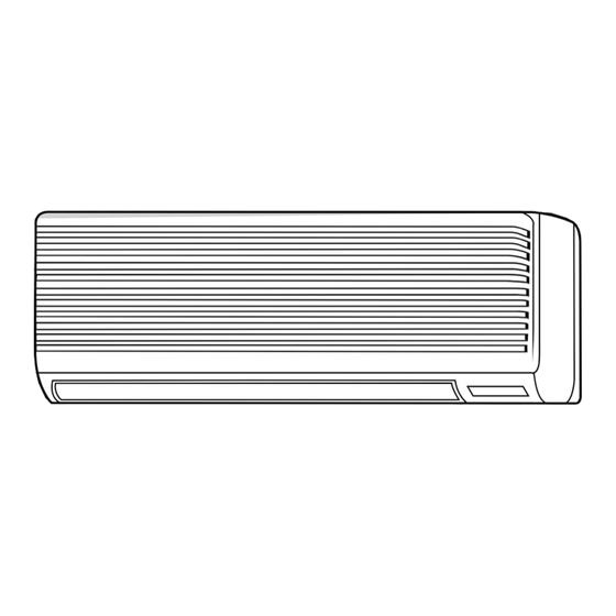
Page 6: Part Names And Functions
PART NAMES AND FUNCTIONS ● Indoor Unit PKFY-P32VGM-E Filter Air intake grille PKFY-P40VGM-E PKFY-P50VGM-E Air intake Auto vane Guide vane Air outlet ● Wired remote controller On the controls are set, the same operation mode can be repeated by simply pressing the ON/OFF button. ●... - Page 7 ● Display “Sensor” indication Displays when the remote controller sensor is used. Day-of-Week For purposes of this explanation, Shows the current day of the week. all parts of the display are shown. During actual operation, only Time/Timer Display the relevant items will be lit. “Locked”...
-
Page 8: Specifications
SPECIFICATIONS 3-1. SPECIFICATION Item PKFY-P40VGM-E PKFY-P50VGM-E PKFY-P32VGM-E Single phase 220V-230V-240V · 50Hz / 220V · 60Hz Power V•Hz Cooling capacity Heating capacity Cooling 0.07 Input Heating 0.07 Cooling 0.32 Current Heating 0.32 Exterior — Plastic , white : <0.70Y 8.59/0.97> (munsell symbol) Height Dimensions... - Page 9 3-2. ELECTRICAL PARTS SPECIFICATIONS Model PKFY-P50VGM-E Symbol PKFY-P40VGM-E PKFY-P32VGM-E Parts name Room temperature thermistor TH21 Resistance 0ºC/15kΩ, 10ºC/9.6kΩ, 20ºC/6.3kΩ, 25ºC/5.4kΩ, 30ºC/4.3kΩ, 40ºC/3.0kΩ Liquid pipe temperature thermistor TH22 Resistance 0ºC/15kΩ, 10ºC/9.6kΩ, 20ºC/6.3kΩ, 25ºC/5.4kΩ, 30ºC/4.3kΩ, 40ºC/3.0kΩ Gas pipe temperature thermistor TH23 Resistance 0ºC/15kΩ, 10ºC/9.6kΩ, 20ºC/6.3kΩ, 25ºC/5.4kΩ, 30ºC/4.3kΩ, 40ºC/3.0kΩ Fuse FUSE 250V 6.3A...
-
Page 10: Outlines And Dimensions
OUTLINES AND DIMENSIONS PKFY-P32VGM-E Unit : mm PKFY-P40VGM-E PKFY-P50VGM-E Air intake 30 or more 180 or more OC310B... -
Page 11: Wiring Diagram
WIRING DIAGRAM PKFY-P32VGM-E PKFY-P40VGM-E PKFY-P50VGM-E Legend Name Symbol Name Symbol Name Symbol Capacitor (fan motor) Pipe temperature detection/Gas Indoor controller board TH23 Thermistor Linear expansion valve CN32 Connector Remote switch (0ºC/15k , 25ºC/5.4k ) Fan motor (with inner thermo) CN41 HA terminal-A Circuit board Vane motor... -
Page 12: Refrigerant System Diagram
REFRIGERANT SYSTEM DIAGRAM PKFY-P32VGM-E PKFY-P40VGM-E PKFY-P50VGM-E Strainer (#50mesh) Gas pipe temperatute thermistor TH23 Gas pipe Liquid pipe temperature thermistor TH22 Flare connection Liquid pipe Heat exchanger Linear expansion valve Strainer (#100mesh) Strainer (#100mesh) Room temperature thermistor TH21 Capacity PKFY-P32VGM-E PKFY-P40VGM-E PKFY-P50VGM-E Item 12.7 (1/2”) or 15.88(5/8”) -
Page 13: Troubleshooting
TROUBLE SHOOTING 7-1. HOW TO CHECK THE PARTS PKFY-P32VGM-E PKFY-P40VGM-E PKFY-P50VGM-E Parts name Check method Room temperature Disconnect the connector then measure the resistance with a tester. thermistor (TH21) (Surrounding temperature 10°C~30°C) Liquid pipe temperature Normal Abnormal thermistor (TH22) Refer to the next page for the details. 4.3k ~9.6k Open or short Gas pipe temperature... - Page 14 <Thermistor Characteristic graph> < Thermistor for lower temperature > Room temperature thermistor(TH21) Thermistor for Liquid pipe temperature thermistor (TH22) lower temperature Gas pipe temperature thermistor (TH23) Thermistor R =15k ± 3% Fixed number of B=3480 ± 2% Rt=15exp { 3480( 273+t 0ºC 10ºC...
- Page 15 <Output pulse signal and the valve operation> Output Output (Phase) Closing a valve : 1 → 2 → 3 → 4 → 1 Opening a valve : 4 → 3 → 2 → 1 → 4 The output pulse shifts in above order. *1.
- Page 16 7-2. FUNCTION OF DIPSWITCH PKFY-P32VGM-E PKFY-P40VGM-E PKFY-P50VGM-E Operation by switch Switch Pole Function Remarks Thermistor<Intake temperature Indoor unit Built-in remote controller Address board detection>position Filter clogging detection Provided Not provided <Initial setting> Filter cleaning sign 2500hr 100hr 1 2 3 4 5 6 7 8 9 10 NOTE: Air intake Effective...
- Page 17 Switch Pole Operation by switch Remarks Address board SW11 1st digit Address can be set while the address unit is stopped. setting SW12 SW11 Address setting should be done when <Initial setting> M-NET remote controller is being used. SW12 SW11 SW12 2nd digit address...
- Page 18 7-3. TEST POINT DIAGRAM 7-3-1. Indoor controller board PKFY-P32VGM-E PKFY-P40VGM-E PKFY-P50VGM-E CN29 Pipe temperature CN2D CN2M CN3A thermistor/Gas (TH23) Connect to the indoor Connect to the terminal block (TB5) Connect to the terminal block (TB15) power board (CN2S) (M-NET transmission connecting wire) (MA-Remote controller connecting wire) 12.5-13.7V DC (Pin 1 (+)) 24-30V DC (non-polar)
- Page 19 7-3-2. Indoor power board PKFY-P32VGM-E PKFY-P40VGM-E PKFY-P50VGM-E CN2S Connect to the indoor power board (CN2D) Between 1 to 3 12.6-13.7V DC (Pin 1 (+)) CNSK Connect to the indoor controller board (CNDK) Between 1 to 3 220-240V AC OC310B...
-
Page 20: Disassembly Procedure
DISASSEMBLY PROCEDURE PKFY-P32VGM-E PKFY-P40VGM-E PKFY-P50VGM-E OPERATION PROCEDURE PHOTOS & ILLUSTRATION (Figure 1) Hook 1. REMOVE THE LOWER SIDE OF THE INDOOR UNIT FROM THE INSTALLATION PLATE (1) Remove the left / right corner box of the indoor unit. (2) Hold and pull down the lower and both ends of the indoor unit, and remove the ▼... - Page 21 OPERATION PROCEDURE PHOTOS & ILLUSTRATION (Photo 4) 4. REMOVING THE VANE MOTOR (1) Disconnect the connector CN6V on the indoor controller Nozzle Set screws board. assembly (2) Remove the 2 screws of the vane motor, disconnect the lead wire and remove the vane motor from the shaft. Lead wire Vane motor 5.
- Page 22 OPERATION PROCEDURE PHOTOS & ILLUSTRATION (Photo 10) 9. REMOVING THE LINE FLOW FAN (1) Remove the terminal block cover. (2) Remove the front panel. (See the photo 1) Heat exchanger (3) Remove the electrical parts box. (See the photo 7) (4) Remove the nozzle assembly.
-
Page 23: Rohs Parts List
RoHS PARTS LIST STRUCTURAL PARTS PKFY-P32VGM-E PKFY-P40VGM-E PKFY-P50VGM-E Recom- Wiring Remarks PKFY- Diagram mended Parts No. Parts Name Specifications (Drawing No.) P32,P40,P50VGM-E Q'ty Symbol FRONT PANEL R01 E05 651 VANE SLEEVE R01 08Y 092 FRONT GRILLE R01 08Y 691 AIR FILTER R01 A32 500 AUTO VANE R01 08Y 002... - Page 24 RoHS PARTS LIST ELECTRICAL PARTS PKFY-P32VGM-E PKFY-P40VGM-E PKFY-P50VGM-E TEMP. ON/OFF 13 14 Wiring Recom- PKFY-P·VGM-E Remarks Specifications Parts No. Parts Name Diagram mended (Drawing No.) Symbol Q'ty FAN MOTOR T7W A02 762 HEAT EXCHANGER R01 J34 480 HEAT EXCHANGER R01 J35 480 R01 J36 480 HEAT EXCHANGER R01 E22 114...
- Page 25 OC310B...
- Page 26 HEAD OFFICE : TOKYO BLDG., 2-7-3, MARUNOUCHI, CHIYODA-KU, TOKYO100-8310, JAPAN ©Copyright 2004 MITSUBISHI ELECTRIC CORPORATION Distributed in Mar. 2013 No. OC310 REVISED EDITION-B Distributed in Jul. 2006 No. OC310 REVISED EDITION-A PDF 8 New publication, effective Mar. 2013 Distributed in Apr. 2004 No. OC310 PDF 9 Specifications are subject to change without notice.
Need help?
Do you have a question about the PKFY Series and is the answer not in the manual?
Questions and answers