Mitsubishi Electric PKFY Series Technical & Service Manual
Hide thumbs
Also See for PKFY Series:
- Technical & service manual (39 pages) ,
- Technical & service manual (28 pages) ,
- Technical & service manual (24 pages)
Table of Contents
Advertisement
Quick Links
SPLIT-TYPE,HEAT PUMP AIR CONDITIONERS
TECHNICAL & SERVICE MANUAL
<Indoor unit>
[ Model names ]
PKFY-P32VGM
PKFY-P40VGM
PKFY-P50VGM
Indoor unit
[ Service Ref. ]
PKFY-P32VGM
PKFY-P40VGM
PKFY-P50VGM
R407C
R22
CONTENTS
1. SAFETY PRECAUTION ............................. 2
2. PART NAMES AND FUNCTIONS ............. 4
3. SPECIFICATIONS ..................................... 6
4. OUTLINES AND DIMENSIONS ................ 8
5. WIRING DIAGRAM .................................... 9
6. REFRIGERANT SYSTEM DIAGRAM ..... 10
7. TROUBLE SHOOTING ............................ 11
8. DISASSEMBLY PROCEDURE ................ 16
9. PARTS LIST ............................................ 19
February 2012
No. OC179
REVISED EDITION-B
Revision:
• The indicated No. of CORNER
COVER (page 19) in the illus-
tration have been corrected in
REVISED EDITION-B.
• Some descriptions have been
modified.
• Please void OC179
REVISED EDITION-A.
Advertisement
Table of Contents

Related Manuals for Mitsubishi Electric PKFY Series


Summary of Contents for Mitsubishi Electric PKFY Series
-
Page 1: Table Of Contents
SPLIT-TYPE,HEAT PUMP AIR CONDITIONERS February 2012 No. OC179 REVISED EDITION-B TECHNICAL & SERVICE MANUAL R407C <Indoor unit> Revision: [ Service Ref. ] [ Model names ] • The indicated No. of CORNER COVER (page 19) in the illus- PKFY-P32VGM PKFY-P32VGM tration have been corrected in REVISED EDITION-B. -
Page 2: Safety Precaution
SAFETY PRECAUTION CAUTIONS RELATED TO NEW REFRIGERANT Cautions for units utilizing refrigerant R407C Do not use the existing refrigerant piping. Use liquid refrigerant to charge the system. The old refrigerant and lubricant in the existing piping If gas refrigerant is used to seal the system, the composition contains a large amount of chlorine which may cause the of the refrigerant in the cylinder will change and performance lubricant deterioration of the new unit. - Page 3 [1] Service tools Use the below service tools as exclusive tools for R407C refrigerant. Tool name Specifications Gauge manifold ·Only for R407C. ·Use the existing fitting SPECIFICATIONS. (UNF7/16) ·Use high-tension side pressure of 3.43MPa·G or over. Charge hose ·Only for R407C. ·Use pressure performance of 5.10MPa·G or over.
-
Page 4: Part Names And Functions
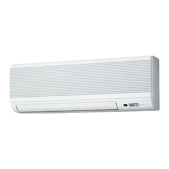
PART NAMES AND FUNCTIONS ● Indoor Unit PKFY-P32VGM PKFY-P40VGM Filter Air intake grill PKFY-P50VGM Air intake Auto vane Guide vane Air outlet ● Remote controller [PAR-F25MA] ● Once the controls are set, the same operation mode can be repeated by simply pressing the on / off button. ●... - Page 5 ● Display In this display example on CENTRALLY CLOCK display FAN SPEED display the bottom left, a condition CONTROLLED display where all display lamps light The current time, start time and stop The selected fan speed is displayed. is shown for explanation time can be displayed in ten-second This indicates when the unit is con- intervals by pressing the time switch...
-
Page 6: Specifications
SPECIFICATIONS 3-1. Specification Unit PKFY-P50VGM Item PKFY-P32VGM PKFY-P40VGM Power source V · Hz Single phase 220-240V 50Hz / 220V 60Hz 5000 Cooling capacity kcal/h 3150 4000 5600 Heating capacity kcal/h 3550 4500 Cooling Power 0.07 consumption Heating 0.07 Cooling 0.32 Current Heating 0.32... - Page 7 3-2. Electrical parts specifications Model Symbol PKFY-P40VGM PKFY-P50VGM PKFY-P32VGM Parts name Transformer (Primary) 50/60Hz 220 - 240V (Secondary) 18.4V 1.7A Room temperature thermistor TH21 Resistance 0C/15k, 10C/9.6k, 20C/6.3k, 25C/5.4k, 30C/4.3k, 40C/3.0k Liquid pipe thermistor TH22 Gas pipe thermistor TH23 Fuse FUSE 250V 6.3A (Indoor controller board)
-
Page 8: Outlines And Dimensions
OUTLINES AND DIMENSIONS Unit : mm PKFY- P32VGM PKFY- P40VGM PKFY- P50VGM Air intake 30 or more 180 or more OC179B... -
Page 9: Wiring Diagram
WIRING DIAGRAM PKFY-P32VGM, PKFY-P40VGM, PKFY-P50VGM Symbol Name Symbol Name Symbol Name Room temperature detection Indoor controller board Thermistor Circuit board TH21 (0 /15 ,25 /5.4 ) CN32 Connector Remote switch Switch Mode selection Pipe temperature detection/Liquid CN41 HA terminal-A Voltage selection TH22 (0 /15 ,25 /5.4 ) CN51... -
Page 10: Refrigerant System Diagram
REFRIGERANT SYSTEM DIAGRAM PKFY-P32VGM PKFY-P40VGM PKFY-P50VGM Strainer (#50mesh) Gas pipe thermistor TH23 Gas pipe Liquid pipe thermistor TH22 Flare connection Heat exchanger Linear expansion valve Strainer (#100mesh) Strainer (#100mesh) Room temperature thermistor TH21 Refrigeration pipe size (Flare connection size) Capacity PKFY-P32VGM, PKFY-P40VGM PKFY-P50VGM Item... -
Page 11: Trouble Shooting
TROUBLE SHOOTING 7-1. How to check PKFY-P32VGM , PKFY-P40VGM , PKFY-P50VGM Parts name Check method Room temperature Disconnect the connector then measure the resistance with a tester. thermistor (TH21) (Surrounding temperature 10°C~30°C) Liquid pipe Normal Abnormal thermistor (TH22) 4.3k ~9.6k Open or short Gas pipe thermistor (TH23) - Page 12 <Thermistor Characteristic graph> < Thermistor for lower temperature > Room temperature thermistor (TH21) Thermistor for Liquid pipe thermistor (TH22) lower temperature Gas pipe thermistor (TH23) Drain sensor (THD) Thermistor R =15k' ± 3% Fixed number of B=3480k ± 2% Rt=15exp { 3480( 273+t 15k' 9.6k'...
- Page 13 <Output pulse signal and the valve operation> Output Output Closing a valve : 1 → 2 → 3 → 4 → 1 (Phase) Opening a valve : 4 → 3 → 2 → 1 → 4 The output pulse shifts in above order. * 1.
- Page 14 7-2. FUNCTION OF DIP SWITCH PKFY-P32VGM , PKFY-P40VGM , PKFY-P50VGM The black square ( ) indicates a switch position. Operation by switch Switch Pole Function Remarks Thermistor<Intake temperature Indoor unit Bult-in remote controller Address board detection>position Filter clogging detection Provided Not provided <Initial setting>...
- Page 15 The black square ( ) indicates a switch position. Switch Pole Operation by switch Remarks SW11 Address board 1st digit Address can be set while the SW12 SW11 address unit is stopped. setting Address setting should be done when network <Initial setting>...
-
Page 16: Disassembly Procedure
DISASSEMBLY PROCEDURE PKFY-P32VGM , PKFY-P40VGM , PKFY-P50VGM OPERATION PROCEDURE PHOTOS & ILLUSTRATION (Figure 1) Hook 1 REMOVING THE LOWER SIDE OF THE INDOOR UNIT FROM THE INSTALLATION PLATE (1) Remove the left / right corner box of the indoor unit. (2) Hold and pull down the lower and both ends of the indoor unit, and remove the ▼... - Page 17 OPERATION PROCEDURE PHOTOS & ILLUSTRATION (Photo 4) 4 REMOVING THE VANE MOTOR (1) Disconnect the connector CN6V on the indoor controller Nozzle board. assembly Set screws (2) Remove the 2 screws of the vane motor, disconnect the lead wire and remove the vane motor from the shaft. Lead wire Vane motor 5 REMOVING THE THERMISTOR...
- Page 18 (Photo 10) 9 REMOVING THE LINE FLOW FAN (1) Remove the terminal block cover. (2) Remove the front panel. (See Photo 1) Heat exchanger (3) Remove the electrical parts box. (See Photo 7) (4) Remove the nozzle assembly. (See Photo 6) (5) Remove the fan motor.
-
Page 19: Parts List
PARTS LIST (non-RoHs compliant) PKFY-P32VGM PKFY-P40VGM STRUCTURAL PARTS PKFY-P50VGM PKFY-P32VGM Wiring Recom- Remarks Parts Name Parts No. Specifications PKFY-P40VGM Diagram mended (Drawing No.) PKFY-P50VGM Symbol Q'ty FRONT PANEL R01 89Y 651 R01 A16 500 AIR FILTER R01 07Y 096 SCREW CAP R01 10Y 658 CORNER COVER R01 08Y 658... - Page 20 PARTS LIST (non-RoHs compliant) PKFY-P32VGM PKFY-P40VGM ELECTRICAL PARTS PKFY-P50VGM FILTER CHECK MODE TEST RUN 11 12 Part numbers that are circled are not shown in the figure. Wiring Recom- PKFY- Remarks Specifications Diagram mended Parts No. Parts Name (Drawing No.) P32VGM P40VGM P50VGM...
- Page 21 OC179B...
- Page 22 HEAD OFFICE : TOKYO BLDG., 2-7-3, MARUNOUCHI, CHIYODA-KU TOKYO 100-8310, JAPAN C Copyright 1998 MITSUBISHI ELECTRIC CORPORATION Distributed in Feb. 2012 No.OC179 REVISED EDITION-B Distributed in Jun. 2000 No.OC179 REVISED EDITION-A 200 Distributed in Dec. 1999 No.OC179 50 New publication, effective Feb. 2012 Distributed in Nov.
Need help?
Do you have a question about the PKFY Series and is the answer not in the manual?
Questions and answers