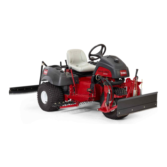
Toro Sand Pro 5040 Operator's Manual
Front lift frame, traction unit, serial no. 311000336 and up
Hide thumbs
Also See for Sand Pro 5040:
- Service manual (262 pages) ,
- Operator's manual (44 pages) ,
- Manual (12 pages)
Advertisement
Quick Links
Download this manual
See also:
Service Manual
Front Lift Frame
Sand Pro
Model No. 08712—Serial No. 311000336 and Up
This product contains a chemical or chemicals known to the State of California
This product complies with all relevant European directives. For details, please see the Declaration of
Incorporation (DOI) at the back of this publication.
Note:
Determine the left and right sides of the machine from the normal operating position.
Setup
Loose Parts
Use the chart below to verify that all parts have been shipped.
Procedure
1
2
3
4
© 2017—The Toro® Company
8111 Lyndale Avenue South
Bloomington, MN 55420
®
/Infield Pro
Proposition 65 Warning
to cause cancer, birth defects, or reproductive harm.
Description
No parts required
No parts required
Straight hydraulic fitting with O-ring
90-degree hydraulic fitting with O-ring
Lift valve
Valve plate
Bolt (1/4 x 3 inches)
Locknut (1/4 inch)
Bolt (#10 x 1-1/4 inches)
Locknut (#10)
Lift lever
Right plow plate
Left plow plate
Bolt (1/2 x 2 inches)
Locknut (1/2 inch)
Hitch frame bracket
Bolt (1/2 x 1-3/4 inches)
Register at www.Toro.com.
®
5040 Traction Unit
WARNING
CALIFORNIA
Qty.
–
–
2
2
1
1
3
3
2
2
1
1
1
4
4
1
2
Form No. 3391-391 Rev B
Operator's Manual
Use
Prepare the machine.
Remove the shrouds.
Install the lift valve.
Install the plow plates.
Original Instructions (EN)
All Rights Reserved *3391-391* B
Printed in the USA
Advertisement

Related Manuals for Toro Sand Pro 5040


Summary of Contents for Toro Sand Pro 5040
- Page 1 Bolt (1/2 x 2 inches) Install the plow plates. Locknut (1/2 inch) Hitch frame bracket Bolt (1/2 x 1-3/4 inches) © 2017—The Toro® Company Register at www.Toro.com. Original Instructions (EN) All Rights Reserved *3391-391* B 8111 Lyndale Avenue South Printed in the USA...
- Page 2 Procedure Description Qty. Hitch frame Bolt (3/8 x 2 inches) Nut (3/8 inch) Capscrew (3/8 x 1-1/2 inches) Locknut (3/8 inch) Cylinder pin Adapter plate Push arm tube Install the push arms and hitch frame. Pin assembly Thread-forming screw Bolt (5/8 x 1-1/2 inches) Washer (1.68-inch outside diameter x 0.65-inch inside diameter) Tube...
-
Page 3: Preparing The Machine
Preparing the Machine No Parts Required Procedure Park the machine on a level surface. Lower the attachments. Engage the parking brake. Shut off the engine and remove the key. g003660 Figure 1 1. Control panel 3. Console mounting bolt locations 2. - Page 4 g003663 Figure 4 1. Straight fitting 3. Lift valve 2. 90-degree fitting Mount the valve assembly, pivot bracket, and g003662 Figure 3 valve plate to the frame with 3 bolts (1/4 x 3 inches) and 3 locknuts (Figure 5). Position the 1.
- Page 5 Remove and discard the 2 bolts securing the front of the steering pivot to the top of the caster fork (Figure Using the caster fork and steering pivot mounting holes, mount the hitch frame bracket to the underside of the caster fork with 2 bolts (1/2 x 1-3/4 inches);...
- Page 6 Insert a cylinder pin into each push arm tube as shown in Figure Insert the push arm tubes onto the right and left plow plates aligning the cylinder pin guides with Installing the Push Arms the holes in the plow plates (Figure Note: If unable to get the push arm tubes...
- Page 7 g028340 Figure 11 Important: Ensure that the existing hoses are routed above the guide, as shown in Figure g018349 Figure 9 1. Hitch frame bracket 3. Hitch frame tube Installing the Hydraulic 2. Hitch frame Cylinder Secure the frame adapter to the hitch frame with a tube, a clevis pin, and a cotter pin (Figure 10).
- Page 8 Installing the Hydraulic Hoses Parts needed for this procedure: Tube assembly Hydraulic hose (Part No. 108-8449) Hydraulic hose (Part No. 108-8453) Hydraulic hose (Part No. 108-8454) g003669 Wire hose holder Figure 12 Thread forming screw (5/16 x 3/4 inch) 1. Hydraulic cylinder 3.
- Page 9 new valve and the vacated fitting on the existing cylinder fitting (Figure 15). Refer to Figure 16 lift valve (Figure 15). Figure 17 for hose routing. Connect the long 90-degree fitting end of the Connect the 45-degree fitting end of hydraulic hydraulic hose, Part No.
- Page 10 g218466 Figure 16 1. Cable tie 2. Hydraulic hose (Part No. 3. Hydraulic hose (Part No. 4. Hydraulic hose (Part No. 108-8449) 108-8453) 108-8454)
- Page 11 g218467 Figure 17 1. Cable tie 3. Hydraulic hose (Part No. 108-8453) 2. Hydraulic hose (Part No. 108-8449) 4. Hydraulic hose (Part No. 108-8454)
- Page 12 WARNING Hydraulic fluid escaping under pressure can penetrate skin and cause injury. • If hydraulic fluid is injected into the Installing the Control Panel skin it must be surgically removed and Lever Guide Plate within a few hours by a doctor familiar with this type of injury.
-
Page 13: Maintenance
Secure the control panel in place with the Authorized Service Dealer or Distributor or go to fasteners previously removed (Figure 19). www.Toro.com for a list of all approved attachments and accessories. Operating Tips • The front lift frame is designed to accept only certain attachments. - Page 14 g003677 Figure 20...
- Page 15 Schematics g218266 Hydraulic schematic 108-2946 (Rev. E)
- Page 16 Notes:...
- Page 17 Notes:...
- Page 18 The method of transmission shall be electronic transmittal. This machinery shall not be put into service until incorporated into approved Toro models as indicated on the associated Declaration of Conformity and in accordance with all instructions, whereby it can be declared in conformity with all relevant Directives.
- Page 19 The Way Toro Uses Information Toro may use your personal information to process warranty claims, to contact you in the event of a product recall and for any other purpose which we tell you about. Toro may share your information with Toro's affiliates, dealers or other business partners in connection with any of these activities. We will not sell your personal information to any other company.
- Page 20 Countries Other than the United States or Canada Customers who have purchased Toro products exported from the United States or Canada should contact their Toro Distributor (Dealer) to obtain guarantee policies for your country, province, or state. If for any reason you are dissatisfied with your Distributor's service or have difficulty obtaining guarantee information, contact the Toro importer.
Need help?
Do you have a question about the Sand Pro 5040 and is the answer not in the manual?
Questions and answers