ABB Relion 650 Series Operation Manual
Version 1.1 ansi
Hide thumbs
Also See for Relion 650 Series:
- Technical manual (754 pages) ,
- Applications manual (382 pages) ,
- Commissioning manual (182 pages)
Table of Contents
Advertisement
Quick Links
Advertisement
Table of Contents

Related Manuals for ABB Relion 650 Series


Summary of Contents for ABB Relion 650 Series
- Page 1 ® Relion 650 SERIES 650 series Version 1.1 ANSI Operation manual...
- Page 3 Document ID: 1MRK 500 093-UUS Issued: November 2019 Revision: A Product version: 1.1 © Copyright 2011 ABB. All rights reserved...
- Page 4 Copyright This document and parts thereof must not be reproduced or copied without written permission from ABB, and the contents thereof must not be imparted to a third party, nor used for any unauthorized purpose. The software or hardware described in this document is furnished under a license and may be used or disclosed only in accordance with the terms of such license.
- Page 5 In case any errors are detected, the reader is kindly requested to notify the manufacturer. Other than under explicit contractual commitments, in no event shall ABB be responsible or liable for any loss or damage resulting from the use of this manual or the application of the equipment.
- Page 6 Directive 2004/108/EC) and concerning electrical equipment for use within specified voltage limits (Low-voltage directive 2006/95/EC). This conformity is the result of tests conducted by ABB in accordance with the product standards EN 50263 and EN 60255-26 for the EMC directive, and with the product standards EN 60255-1 and EN 60255-27 for the low voltage directive.
-
Page 7: Table Of Contents
Single-line diagram........................39 Authorization............................. 43 Communication..........................44 PCM600 tool............................45 4.4.1 Connectivity packages........................45 4.4.2 PCM600 and IED connectivity package version............... 45 Cyber security guidelines........................ 46 4.5.1 About cyber security guidelines....................46 650 series Operation manual © Copyright 2011 ABB. All rights reserved... - Page 8 Operating procedures..................67 Monitoring............................67 7.1.1 Indications............................67 7.1.1.1 Using auto-indication messages................... 67 7.1.1.2 Monitoring alarm data......................68 7.1.1.3 Monitoring an internal IED fault ....................69 7.1.1.4 Monitoring condition monitoring data................70 650 series Operation manual © Copyright 2011 ABB. All rights reserved...
- Page 9 8.2.2 Warnings............................83 8.2.3 Additional indications........................84 Correction procedures........................84 8.3.1 Changing and setting the password..................84 8.3.2 Identifying IED application problems..................84 8.3.2.1 Inspecting the wiring....................... 84 Section 9 Glossary......................89 650 series Operation manual © Copyright 2011 ABB. All rights reserved...
-
Page 11: Introduction
The operator must be trained in and have a basic knowledge of how to operate protection equipment. The manual contains terms and expressions commonly used to describe this kind of equipment. 650 series Operation manual © Copyright 2011 ABB. All rights reserved... -
Page 12: Product Documentation
IED should be commissioned. The operation manual contains instructions on how to operate the IED once it has been commissioned. The manual provides instructions for monitoring, controlling and setting the IED. 650 series Operation manual © Copyright 2011 ABB. All rights reserved... -
Page 13: Document Revision History
1MRK 505 265-TUS Documents related to REL650 Identity number Application manual 1MRK 506 325-UUS Technical manual 1MRK 506 326-UUS Commissioning manual 1MRK 506 327-UUS Table continues on next page 650 series Operation manual © Copyright 2011 ABB. All rights reserved... - Page 14 Communication protocol manual, IEC 60870-5-103 1MRK 511 243-UUS Point list manual, DNP3 1MRK 511 244-UUS Engineering manual 1MRK 511 245-UUS Operation manual 1MRK 500 093-UUS Installation manual 1MRK 514 014-UUS 650 series Operation manual © Copyright 2011 ABB. All rights reserved...
-
Page 15: Symbols And Conventions
To save the changes in non-volatile memory, select Yes and press • Parameter names are shown in italics, for example: Operation setting. The function can be enabled and disabled with the 650 series Operation manual © Copyright 2011 ABB. All rights reserved... -
Page 16: Functions Included In 650 Series Ieds
IEC 61850 / Function ANSI Function description block name Current protection PHPIOC Instantaneous phase overcurrent protection SPTPIOC Instantaneous phase overcurrent protection OC4PTOC 51/67 Four-step phase overcurrent protection Table continues on next page 650 series Operation manual © Copyright 2011 ABB. All rights reserved... - Page 17 Control and monitoring functions IEC 61850 / Function ANSI Function description block name Control SESRSYN Synchrocheck, energizing check and synchronizing SMBRREC Autorecloser STBRREC Autorecloser Table continues on next page 650 series Operation manual © Copyright 2011 ABB. All rights reserved...
- Page 18 IED commands with position and select for IEC60870-5-103 Secondary system supervision CCSRDIF Current circuit supervision SDDRFUF Fuse failure supervision TCSSCBR Breaker close/trip circuit monitoring Logic Table continues on next page 650 series Operation manual © Copyright 2011 ABB. All rights reserved...
- Page 19 Phase-neutral voltage measurement AISVBAS Function block for service values presentation of the analog inputs TM_P_P2 Function block for service value presentation of primary analog inputs 600TRM Table continues on next page 650 series Operation manual © Copyright 2011 ABB. All rights reserved...
- Page 20 IED status for IEC60870-5-103 I103SUPERV Supervision status for IEC60870-5-103 I103USRDEF Status for user defiend signals for IEC60870-5-103 Metering PCGGIO Pulse counter logic ETPMMTR Function for energy calculation and demand handling 650 series Operation manual © Copyright 2011 ABB. All rights reserved...
- Page 21 Function description block name Basic functions included in all products INTERRSIG Self-supervision with internal event list SELFSUPEVLST Self-supervision with internal event list TIMESYNCHGEN Time synchronization Table continues on next page 650 series Operation manual © Copyright 2011 ABB. All rights reserved...
- Page 22 Global base values for settings DOSFRNT Denial of service, frame rate control for front port DOSLAN1 Denial of service, frame rate control for LAN1 port DOSSCKT Denial of service, socket flow control 650 series Operation manual © Copyright 2011 ABB. All rights reserved...
-
Page 23: Safety Information
Do not touch circuitry during operation. Potentially lethal voltages and currents are present. M2364-2 v1 Always use suitable isolated test pins when measuring signals in open circuitry. Potentially lethal voltages and currents are present. 650 series Operation manual © Copyright 2011 ABB. All rights reserved... -
Page 24: Caution Signs
M2695-2 v2 Always transport PCBs (modules) using certified conductive bags. M2696-2 v1 Do not connect live wires to the IED. Internal circuitry may be damaged 650 series Operation manual © Copyright 2011 ABB. All rights reserved... -
Page 25: Note Signs
Note signs IP1497-1 v1.1.1 M19-2 v3.1.1 Observe the maximum allowed continuous current for the different current transformer inputs of the IED. See technical data. 650 series Operation manual © Copyright 2011 ABB. All rights reserved... -
Page 27: Environmental Aspects
These handlers can sort the material by using dedicated sorting processes and dispose of the product according to the local requirements. 650 series Operation manual © Copyright 2011 ABB. All rights reserved... - Page 28 Parts Material Unit Metallic plates, parts and screws Steel Plastic parts , LCP LHMI display module Various Package Cardboard Attached material Manuals Paper 1) Polycarbonate 2) Liquid crystal polymer 650 series Operation manual © Copyright 2011 ABB. All rights reserved...
-
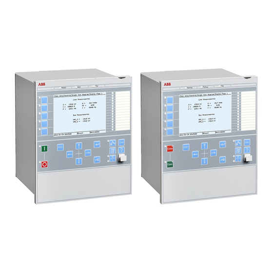
Page 29: 650 Series Overview
The LHMI is used for setting, monitoring and controlling . 4.1.1 Display GUID-55739D4F-1DA5-4112-B5C7-217AAF360EA5 v3 The LHMI includes a graphical monochrome display with a resolution of 320 x 240 pixels. The character size can vary. 650 series Operation manual © Copyright 2011 ABB. All rights reserved... - Page 30 If text, pictures or other items do not fit in the display, a vertical scroll bar appears on the right. The text in content area is truncated from the beginning if it does not fit in the display horizontally. Truncation is indicated with three dots. 650 series Operation manual © Copyright 2011 ABB. All rights reserved...
- Page 31 The LED is connected to the required signal with PCM600. GUID-11D6D98C-A2C9-4B2C-B5E0-FF7E308EC847 V1 EN-US Figure 5: Function button panel The alarm LED panel shows on request the alarm text labels for the alarm LEDs. 650 series Operation manual © Copyright 2011 ABB. All rights reserved...
-
Page 32: Leds
The keypad also contains programmable push-buttons that can be configured either as menu shortcut or control buttons. 650 series Operation manual © Copyright 2011 ABB. All rights reserved... - Page 33 LHMI keypad with object control, navigation and command push-buttons and RJ-45 communication port 1...5 Function button Close Open Escape Left Down Right Enter Remote/Local Uplink LED Not in use Multipage Menu Clear Help 650 series Operation manual © Copyright 2011 ABB. All rights reserved...
- Page 34 Changing the active digit of a parameter when entering a new setting value. Right • Activating the authorization procedure, when the user is not logged in. • Logging out, when the user is currently logged in. 650 series Operation manual © Copyright 2011 ABB. All rights reserved...
-
Page 35: Local Hmi Functionality
The protection indicator LEDs are Normal, Pickup and Trip. Table 12: Normal LED (green) LED state Description Auxiliary supply voltage is disconnected. Normal operation. Flashing Internal fault has occurred. 650 series Operation manual © Copyright 2011 ABB. All rights reserved... - Page 36 LatchedAck-F-S sequence: The activation signal is on, or it is off but the indication has not been acknowledged. • LatchedAck-S-F sequence: The indication has been acknowledged, but the activation signal is still on. 650 series Operation manual © Copyright 2011 ABB. All rights reserved...
- Page 37 BUS1 V PKUP GRP2_LED5 Yellow LED BUS2 V PKUP GRP2_LED6 Yellow LED 51 51N 46 PKUP GRP2_LED7 Yellow LED 52PD PICKUP GRP2_LED8 GRP2_LED9 GRP2_LED10 GRP2_LED11 GRP2_LED12 GRP2_LED13 GRP2_LED14 GRP2_LED15 650 series Operation manual © Copyright 2011 ABB. All rights reserved...
- Page 38 Yellow LED 51 PICKUP GRP2_LED4 Yellow LED 51N PICKUP GRP2_LED5 Yellow LED 59 PICKUP GRP2_LED6 Yellow LED 52PD PICKUP GRP2_LED7 GRP2_LED8 GRP2_LED9 GRP2_LED10 GRP2_LED11 GRP2_LED12 Table continues on next page 650 series Operation manual © Copyright 2011 ABB. All rights reserved...
- Page 39 Red LED STEPUP XFMR TRIP GRP1_LED11 Red LED 52PD TRIP GRP1_LED12 Red LED 50BF TRIP GRP1_LED13 Red LED EXTERNAL TRIP GRP1_LED14 Yellow LED P&Q ALARM GRP1_LED15 Yellow LED VOLT ALARM 650 series Operation manual © Copyright 2011 ABB. All rights reserved...
- Page 40 Red LED GND PROT TRIP GRP1_LED4 Red LED 85 PROT TRIP GRP1_LED5 Red LED 59/27 PROT TRIP GRP1_LED6 Red LED 50BF PROT TRIP GRP1_LED7 GRP1_LED8 Table continues on next page 650 series Operation manual © Copyright 2011 ABB. All rights reserved...
- Page 41 Z BLOCK GRP3_LED11 Yellow LED V BLOCK GRP3_LED12 GRP3_LED13 Yellow LED BKR ALARMS GRP3_LED14 Yellow LED TCS ALARM GRP3_LED15 Red LED BAT SUP ALARM Yellow LED BAT SUP PICKUP 650 series Operation manual © Copyright 2011 ABB. All rights reserved...
- Page 42 Yellow LED 51N/67N PICKUP GRP2_LED7 Yellow LED 59 PICKUP GRP2_LED8 Yellow LED 52PD PICKUP GRP2_LED9 Yellow LED 46 PICKUP GRP2_LED10 Yellow LED 26 PICKUP GRP2_LED11 GRP2_LED12 GRP2_LED13 GRP2_LED14 GRP2_LED15 650 series Operation manual © Copyright 2011 ABB. All rights reserved...
- Page 43 GRP2_LED4 Yellow LED T2 84 CMDERR GRP2_LED5 Yellow LED T2 84 TCERRAL GRP2_LED6 Yellow LED T2 84 CONVERR GRP2_LED7 Yellow LED T2 84 HIDIFPOS Table continues on next page 650 series Operation manual © Copyright 2011 ABB. All rights reserved...
-
Page 44: Parameter Management
GUID-FD72A445-C8C1-4BFE-90E3-0AC78AE17C45 v7 The RJ-45 port in the LHMI enables front communication. • The green uplink LED on the left is lit when the cable is successfully connected to the port. 650 series Operation manual © Copyright 2011 ABB. All rights reserved... -
Page 45: Single-Line Diagram
PCM600 to front port. 4.1.4.4 Single-line diagram GUID-2CB16ADA-AF80-42FA-9485-BC7FD33DAEC6 v3 Single-line diagram is used for bay monitoring and/or control. It shows a graphical presentation of the bay which is configured with PCM600. 650 series Operation manual © Copyright 2011 ABB. All rights reserved... - Page 46 Section 4 1MRK 500 093-UUS A 650 series overview Single-line diagram for REB650 ANSI11000179 V1 EN-US Figure 9: Single-line diagram for REB650 (A03A) 650 series Operation manual © Copyright 2011 ABB. All rights reserved...
- Page 47 1MRK 500 093-UUS A Section 4 650 series overview Single-line diagram for REC650 ANSI11000181 V1 EN-US ANSI11000180 V1 EN-US Figure 10: Single-line diagram for REC650 (A07 and A01A) 650 series Operation manual © Copyright 2011 ABB. All rights reserved...
- Page 48 650 series overview Single-line diagram for REG650 ANSI11000182 V1 EN-US Figure 11: Single-line diagram for REG650(B05A) Single-line diagram for REL650 ANSI11000183 V1 EN-US Figure 12: Single-line diagram for REL650(A01A) 650 series Operation manual © Copyright 2011 ABB. All rights reserved...
-
Page 49: Authorization
The IED users can be created, deleted and edited only with PCM600. One user can belong to one or several user categories. At delivery, the user has full access until users are created with PCM600. Logging on is not required for the LHMI. 650 series Operation manual © Copyright 2011 ABB. All rights reserved... -
Page 50: Communication
The IED supports SNTP, DNP3 and IRIG-B time synchronization methods with a time-stamping resolution of 1 ms. IEC 60870-5-103 has time-stamping resolution of ± 5 ms. The IED supports the following time synchronization methods with a timestamping resolution of 1 650 series Operation manual © Copyright 2011 ABB. All rights reserved... -
Page 51: Pcm600 Tool
GUID-4F228406-07FE-4990-9F65-C4B316B35221 v2 • Protection and Control IED Manager PCM600 Ver. 2.3 + Hotfix or later • ABB 650 Series IED Connectivity Package Ver. 1.1 or later • ABB REB650 1.1.0 Module Ver. 1.0 or later • ABB REC650 1.1.0 Module Ver. 1.0 or later •... -
Page 52: Cyber Security Guidelines
Section 4 1MRK 500 093-UUS A 650 series overview • ABB REL650 1.1.0 Module Ver. 1.0 or later • ABB REQ650 1.1.0 Module Ver. 1.0 or later • ABB RET650 1.1.0 Module Ver. 1.0 or later Download connectivity packages from the ABB web site http://www.abb.com/substationautomation... -
Page 53: Internet Protocol Ports Security Guideline
Protocol Default state Service Comment open File transfer protocol open DHCP Front port only open IEC 61850 MMS communication 7001 open Proprietary for PCM600 Table continues on next page 650 series Operation manual © Copyright 2011 ABB. All rights reserved... - Page 54 Internet, the 650 series Ethernet communication must be protected against illegal access. This protection must be handled by external devices to setup a secure virtual private network (VPN). 650 series Operation manual © Copyright 2011 ABB. All rights reserved...
-
Page 55: Using The Hmi
Enter the password when prompted digit by digit and select OK. • Activate the digit to be entered with • Enter the character with Upper and lower case letters are also found by scrolling with the vertical arrows. 650 series Operation manual © Copyright 2011 ABB. All rights reserved... -
Page 56: Logging Off
Manual logoff is also possible. Press To confirm logoff, select Yes and press A071188 V2 EN-US Figure 18: Logging off • To cancel logoff, press 650 series Operation manual © Copyright 2011 ABB. All rights reserved... -
Page 57: Turning The Display Backlight On
Identifying the device AMU0600422 v5 The IED information includes detailed information about the device, such as revision and serial number. Select Main menu/Diagnostics/IED Status/Product identifiers. Select a submenu with 650 series Operation manual © Copyright 2011 ABB. All rights reserved... -
Page 58: Adjusting The Display Contrast
AMU0600410 v5 Adjust the display contrast anywhere in the menu structure to obtain optimal readability. • To increase the contrast, press simultaneously • To decrease the contrast, press simultaneously 650 series Operation manual © Copyright 2011 ABB. All rights reserved... -
Page 59: Changing The Local Hmi Language
To move downwards in the menu tree, press • To move upwards in the menu tree, press • To enter setting mode, press • To leave setting mode without saving, press 650 series Operation manual © Copyright 2011 ABB. All rights reserved... -
Page 60: Menu Structure
5.1.8.3 Changing the default view GUID-068D31CD-D53C-48F4-817C-EAD8E33C0A0C v6 The default view of the display is Main menu unless set otherwise. 650 series Operation manual © Copyright 2011 ABB. All rights reserved... -
Page 61: Using Function Buttons
The panel is also closed after pressing a function button configured for a menu shortcut. The function buttons are configured with PCM600. For more information, see PCM600 documentation. 650 series Operation manual © Copyright 2011 ABB. All rights reserved... -
Page 62: Using The Single-Line Diagram
Select the single-line diagram for the default view in Main menu/ Configuration/HMI/Screen/1:SCREEN/DefaultScreen. 5.1.11 Browsing setting values GUID-81116DC8-1E66-4144-920F-07C79F1C76B0 v2 Select Main menu/Settings/IED Settings and press Press and then to activate the setting group number selection. 650 series Operation manual © Copyright 2011 ABB. All rights reserved... -
Page 63: Editing Values
Editing values GUID-8BF4B799-54A7-4224-BC11-0BCE3129B811 v3 • To edit values, log in with the appropriate user rights. If the user rights are not sufficient for editing values, the login dialog opens. 650 series Operation manual © Copyright 2011 ABB. All rights reserved... -
Page 64: Editing Numerical Values
Another press of sets the value to the lower or higher limit. The symbol in front of the value is ↕, when the previous value is shown. 650 series Operation manual © Copyright 2011 ABB. All rights reserved... -
Page 65: Editing String Values
Editable values are stored in the non-volatile flash memory. Most of the parameter changes take effect immediately after storing, but some parameter changes require application restart. Values stored in the flash memory remain in effect after reboot as well. 650 series Operation manual © Copyright 2011 ABB. All rights reserved... -
Page 66: Clearing And Acknowledging
Events and alarms assigned to alarm LEDs are cleared with the Clear button as well. Press to activate the Clear view. 650 series Operation manual © Copyright 2011 ABB. All rights reserved... -
Page 67: Using The Local Hmi Help
Scroll the text with if the help text exceeds the display area. To close the help, press The help dialog is also closed when the display timeout expires. 650 series Operation manual © Copyright 2011 ABB. All rights reserved... -
Page 69: Ied Operation
Document the disturbance before clearing the information from the IED. Only authorized and skilled personnel should analyze possible errors and decide on further actions. Otherwise, stored disturbance data can be lost. 650 series Operation manual © Copyright 2011 ABB. All rights reserved... -
Page 70: Dfr Recording Triggering
Document all the recorded data from the IED before resetting the tripping and IED lockout functions. IED parametrization GUID-F3F7C6D0-1A2B-487B-8291-C5C346F56C3E v6 IED parameters are set via the LHMI or PCM600. 650 series Operation manual © Copyright 2011 ABB. All rights reserved... -
Page 71: Ied Settings For Ied Functionality
IED settings can be designed for various operation conditions by defining different setting values to different setting groups. The active setting group can be changed by the IED application or manually via the LHMI or PCM600. 650 series Operation manual © Copyright 2011 ABB. All rights reserved... -
Page 73: Operating Procedures
The message contains the same information that is available for disturbance recordings. Press to see more detailed information. Press to close the auto-indication message without clearing it or press to activate the Clear view and to clear messages. 650 series Operation manual © Copyright 2011 ABB. All rights reserved... -
Page 74: Monitoring Alarm Data
Press to open a dialog box that shows more detailed information about the selected alarm. 650 series Operation manual © Copyright 2011 ABB. All rights reserved... -
Page 75: Monitoring An Internal Ied Fault
Figure 34: Alarm data 7.1.1.3 Monitoring an internal IED fault GUID-67B6F8FD-3E2B-4EA6-8822-539F7FA3678B v2 The flashing green LED indicates an internal IED fault. The fault messages are found in the LHMI menu. 650 series Operation manual © Copyright 2011 ABB. All rights reserved... -
Page 76: Monitoring Condition Monitoring Data
Measured values AMU0600431 v5 Measured values can be accessed through the LHMI. 7.1.2.2 Using the local HMI for monitoring AMU0600432 v5 Select Main menu/Measurements to monitor measured and calculated values. 650 series Operation manual © Copyright 2011 ABB. All rights reserved... -
Page 77: Recorded Data
The disturbance recorder is now triggered. 7.1.3.2 Monitoring disturbance recorder data GUID-CBA8221F-A0F8-4043-98D7-577830F29F7F v5 Read individual disturbance recordings from the IED with the PCM600 software to monitor disturbance recorder data. 650 series Operation manual © Copyright 2011 ABB. All rights reserved... -
Page 78: Controlling And Uploading Dfr Recorder Data
To select a category and view the items under it, press and then 7.1.3.3 Controlling and uploading DFR recorder data GUID-E128266D-1DB5-4437-963F-D3DE8FF0FF32 v7 DFR recorder data can be controlled and read with PCM600. 650 series Operation manual © Copyright 2011 ABB. All rights reserved... -
Page 79: Monitoring Events
7.1.4 Remote monitoring GUID-4813E67F-5F17-48A7-A083-27E006A5B386 v1 The IED supports comprehensive remote monitoring. 7.1.4.1 Monitoring the IED remotely GUID-D1DA8B48-DA40-4E9D-9593-E699371EBBD7 v6 Use the PCM600 tool to operate the IED remotely. 650 series Operation manual © Copyright 2011 ABB. All rights reserved... -
Page 80: Controlling
Switch object is in substituted state. Switch object is interlocked. Press to open or to close the object. GUID-5C31AE86-374C-49E2-BC49-B747DC41F2D6 V1 EN-US Figure 40: Selecting an object Press to confirm the operation. 650 series Operation manual © Copyright 2011 ABB. All rights reserved... -
Page 81: Resetting The Ied
Events and alarms assigned to alarm LEDs can also be cleared with the Clear button. Press to activate the Clear view. All the items that can be cleared are shown. 650 series Operation manual © Copyright 2011 ABB. All rights reserved... -
Page 82: Changing The Ied Functionality
IED settings are planned in advance for different operation conditions by calculating setting values to different setting groups. The active setting group can be changed by the IED application or manually from the menu. Select Main menu/Settings/Activate setting group/1:SETGRPS and press 650 series Operation manual © Copyright 2011 ABB. All rights reserved... -
Page 83: Browsing And Editing Setting Group Values
Remember to document the changes you make. 7.4.1.2 Browsing and editing setting group values GUID-5624E7E4-1D14-469A-BF86-8BD560B72F9D v2 Select Main menu/Settings/IED setting and press Setting group 1 is the default setting group to be edited. 650 series Operation manual © Copyright 2011 ABB. All rights reserved... - Page 84 Categories available in the list depend on the configuration configured with PCM600. GUID-18645E71-B6E8-401B-B24E-A8D204876ACF V1 EN-US Figure 47: Selecting the function category To browse the function blocks, scroll the list with 650 series Operation manual © Copyright 2011 ABB. All rights reserved...
- Page 85 The active setting group is marked with an asterisk *. GUID-B3180332-3CDC-44A7-88F1-68D07BCA23C5 V1 EN-US Figure 49: Changing the setting value Press to change the value. Confirm the change with 650 series Operation manual © Copyright 2011 ABB. All rights reserved...
-
Page 86: Activating Leds
Select an Alarm LED with Press to confirm the selection and to change the Alarm LED mode. Press to change the value and to confirm the selection. For more information, see PCM600 documentation. 650 series Operation manual © Copyright 2011 ABB. All rights reserved... -
Page 87: Troubleshooting
Inspect the IED visually. • Inspect the IED visually to find any physical error causes. • If you can find some obvious physical damage, contact ABB for repair or replacement actions. Check whether the error is external or internal. •... -
Page 88: Checking The Time Synchronization
The list is updated by leaving the Internal events menu and then selecting it again. The current status of the internal fault signals can also be checked via the LHMI in Main menu/Diagnostics/IED status. 650 series Operation manual © Copyright 2011 ABB. All rights reserved... -
Page 89: Warnings
Additional information Warning IEC 61850 has not IEC 61850 Error succeeded in some actions such as reading the configuration file, startup etc. Warning Error in DNP3 DNP3 Error communication. 650 series Operation manual © Copyright 2011 ABB. All rights reserved... -
Page 90: Additional Indications
However, even though the phase current or voltage connections to IED terminals might be correct, wrong polarity of one or more measurement transformers can cause problems. 650 series Operation manual © Copyright 2011 ABB. All rights reserved... - Page 91 GUID-BBAEAF55-8D01-4711-A71D-BBC76B60BA3D V1 EN-US Figure 51: Testing output contacts using the voltage drop method Contact current 2 Contact voltage drop 3 Load 4 Supply voltage 650 series Operation manual © Copyright 2011 ABB. All rights reserved...
- Page 92 0 of the output, and in PCM600 a lit or dimmed diode. The second signal is the status Forced or Normal or Forced. Forced status is only achieved when the BO is set to operated on the LHMI. 650 series Operation manual © Copyright 2011 ABB. All rights reserved...
- Page 93 As a result, practically the full voltage is available at the load. 650 series Operation manual © Copyright 2011 ABB. All rights reserved...
-
Page 95: Glossary
Central processor unit Carrier receive Cyclic redundancy check CROB Control relay output block Carrier send 650 series Operation manual © Copyright 2011 ABB. All rights reserved... - Page 96 Electrical and functional description for digital lines used by local telephone companies. Can be transported over balanced and unbalanced lines Communication interface module with carrier of GPS receiver module Graphical display editor within PCM600 650 series Operation manual © Copyright 2011 ABB. All rights reserved...
- Page 97 Ingression protection, according to IEC standard, level IP40-Protected against solid foreign objects of 1mm diameter and greater. IP 54 Ingression protection, according to IEC standard, level IP54-Dust-protected,protected againstsplashing water. 650 series Operation manual © Copyright 2011 ABB. All rights reserved...
- Page 98 Parameter setting tool within PCM600 PT ratio Potential transformer or voltage transformer ratio PUTT Permissive underreach transfer trip RASC Synchrocheck relay, COMBIFLEX Relay characteristic angle RFPP Resistance for phase-to-phase faults 650 series Operation manual © Copyright 2011 ABB. All rights reserved...
- Page 99 FTP, UDP and RDP. TNC connector Threaded Neill-Concelman, a threaded constant impedance version of a BNC connector TPZ, TPY, TPX, TPS Current transformer class according to IEC User management tool 650 series Operation manual © Copyright 2011 ABB. All rights reserved...
- Page 100 Three times zero-sequence current. Often referred to as the residual or the -fault current Three times the zero sequence voltage. Often referred to as the residual voltage or the neutral point voltage 650 series Operation manual © Copyright 2011 ABB. All rights reserved...
- Page 102 ABB AB Substation Automation Products SE-721 59 Västerås, Sweden Phone +46 (0) 21 32 50 00 Scan this QR code to visit our website www.abb.com/substationautomation © Copyright 2011 ABB. All rights reserved.
Need help?
Do you have a question about the Relion 650 Series and is the answer not in the manual?
Questions and answers