
Related Manuals for Honeywell HEN04112


Summary of Contents for Honeywell HEN04112
- Page 1 Performance Series Full PoE Network Video Recorder HEN04112 HEN08112 HEN16122 HEN04122 HEN08122 HEN16142 HEN04102 HEN08142 HEN16162 HEN08102 HEN16102 User Guide Document 800-21090V2 – Rev A – 03/2016...
- Page 3 User Guide...
- Page 4 Revisions Issue Date Revisions 09/2015 New document based on 800-18160V2. V1 Rev A 10/2015 Added two notes in the Camera Configuration chapter. V2 Rev A 03/2016 Amended the part numbers. Amended the product description. Added the Smart Search section in the Playing Back Video section. Amended some Specifications. Added the appendix about MAXPRO Cloud.
- Page 5 Cautions and Warnings Installation and servicing should be performed only by qualified and experienced technicians to conform to all local codes and to maintain your warranty. WARNING Use only with the supplied power converters. The Ethernet connection is not intended to be connected to an exposed (outside plant) network. CAUTION There is a risk of explosion if the battery is replaced by an incorrect type.
- Page 6 Correct Disposal of this Product (applicable in the European Union and other European countries with separate collection systems). This product should be disposed of, at the end of its useful life, as per applicable local laws, regulations, and procedures. www.honeywell.com/security...
- Page 7 Unauthorized substitutions may result in fire, electric shock or other hazards. Warranty and Service Subject to the terms and conditions listed on the Product warranty, during the warranty period Honeywell will repair or replace, at its sole option, free of charge, any defective products returned prepaid.
- Page 8 Be sure to have the model number, serial number, and the nature of the problem available for the technical service representative. Prior authorization must be obtained for all returns, exchanges, or credits. Items shipped to Honeywell without a clearly identified Return Merchandise Authorization (RMA) number may be refused.
- Page 9 Table 1-1 List of Symbols Symbol Explanation The Lead-free symbol. This symbol indicates that the product does not contain lead (Pb). The CCC compliance logo. This logo indicates that the product conforms with the China Compulsory Certification guidelines. The Environment Friendly Use-period symbol. This symbol indicates the length of time that this electronic product can used without harming the environment.
- Page 10 Table 1-1 List of Symbols Symbol Explanation This symbol is used to direct attention to important information. This symbol warns that the corresponding action could result in an electric shock. This symbol indicates On/Standby functionality of the corresponding control/button/switch. www.honeywell.com/security...
-
Page 11: Table Of Contents
Contents | 11 Contents About This Document ..........Overview of Contents. - Page 12 To configure IPC external alarms........110 To set up alarm input detection periods ......111 www.honeywell.com/security...
- Page 13 Contents | 13 To set up alarm input event actions ....... . 112 Configuring No Signal Alarm Events .
- Page 14 Index ............177 www.honeywell.com/security...
- Page 15 Figures | 15 Figures Figure 1-1 NVR Front Panel ......... . 27 Figure 1-2 NVR Back Panel .
- Page 16 Tour Configuration Tab ........131 www.honeywell.com/security...
- Page 17 Figures | 17 Figure 10-7 RS232 Configuration Window ........132 Figure 10-8 Modify User Account Configuration Tab .
- Page 18 18 | Performance Series Full PoE Network Video Recorder User Guide www.honeywell.com/security...
- Page 19 Tables | 19 Tables Table 1-1 List of Symbols ......... . . Table 1-1 IP Cameras Features .
- Page 20 20 | Performance Series Full PoE Network Video Recorder User Guide www.honeywell.com/security...
-
Page 21: About This Document
About This Document This document introduces the Honeywell Performance Series Full PoE Network Video Recorder. It explains how to install and operate the Performance Series Full PoE Network Video Recorder. This document is intended for installers and users. Overview of Contents This document contains the following chapters and appendixes: •... -
Page 22: Related Documents
Describes the physical setup of a HBD2PR1(X) ball IR Bullet IP Camera Quick Installation camera. Guide Performance Series IP Cameras User 800-18161 Describes the Performance Series IP Cameras, how to Guide install them, how to configure them, and how to operate them. www.honeywell.com/security... -
Page 23: Typographical Conventions
| 23 Typographical Conventions This document uses the following typographical conventions: Font What it represents Example Ctrl+C Helvetica Keys on the keyboard Press Lucida Values of editable fields that are mentioned in the The Time from field can be set to Hours:Minute:Seconds. - Page 24 24 | Performance Series Full PoE Network Video Recorder User Guide www.honeywell.com/security...
-
Page 25: Introduction
Introduction This chapter covers: • An overview of the IP Cameras on page 25 • The features of the IP Cameras on page 26 • The components of the NVR on page 27 • An overview of the USB mouse and its operation on page •... -
Page 26: Features Of The Ip Cameras
Internet connection. Backup • Supports backing up video, through the network, to a USB 2.0 device. The recorded files can be saved on the network storage server, on a peripheral USB 2.0 device, or to a burner, for example. www.honeywell.com/security... -
Page 27: Network Video Recorder Components
Introduction | 27 Table 1-1 IP Cameras Features Category Features Network Management • Supports NVR configuration and management through the Ethernet. • Supports device management through the Internet. Peripheral Equipment • Supports peripheral equipment management such as Management protocol setup and port connection. •... - Page 28 • Increase or decrease the current number. • Assistant function such as the PTZ menu (not supported). Left/Right • Shift the currently active control, then move left or right. • Playback mode: Click to control the playback bar. www.honeywell.com/security...
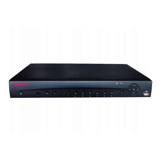
- Page 29 Introduction | 29 Table 1-2 NVR Front Panel Components Component Name Icon Function Enter ENTER • Confirm the current operation. • Go to the Default button. • Go to the Menu. USB 2.0 Port Connect to a USB 2.0 storage device, USB 2.0 mouse or CD/DVD burner.
- Page 30 Media Interface It transmits uncompressed high-definition video and multiple-channel data to the display device’s HDMI port. VGA Video Output VGA video output port. Outputs the analog video Port signal. It can connect to the monitor for viewing analog video. www.honeywell.com/security...
- Page 31 Introduction | 31 Table 1-3 NVR Back Panel Components Icon/Marker Port/Component Connection Function Name Alarm Input Port • Receives the signals from the external alarm sources. Two types: NO (normally open), NC (normally closed). • When your alarm input device is using external power, please make sure the device and the NVR have the same ground.
-
Page 32: Mouse Operation
Click the key corresponding to the letter/number/special character that you want to input in the text box. • To switch between lowercase and uppercase letters, click Shift. • To delete the previous character, click the key. • To insert a space, click the key. Click Enter to close the on-screen keyboard. www.honeywell.com/security... -
Page 33: Remote Control Operation
Introduction | 33 Remote Control Operation It is strongly recommended to use a mouse to operate the NVR. However, you can also use the supplied IR remote control. The following table describes basic remote control operations. Figure 1-5 Remote Control Functions: Button Action Power... - Page 34 34 | Performance Series Full PoE Network Video Recorder User Guide www.honeywell.com/security...
-
Page 35: Getting Started
• Terminal block connectors (×2) • Power adapter and cable • Screws (×10) • Mouse • Serial ATA (SATA) cable* If any of the items listed above are missing or damaged, contact your Honeywell dealer immediately. 800-21090V2 - A - 03/2016... -
Page 36: Connecting External Devices
Step 8: Connect the power cable Connect the supplied 12 V DC power adapter to the power input. Use of an uninterruptible power supply (UPS) is strongly recommended. Typical NVR Installation The following diagram shows a typical NVR installation: www.honeywell.com/security... - Page 37 Getting Started | 37 Figure 2-1 Typical NVR Installation 800-21090V2 - A - 03/2016...
-
Page 38: Starting And Shutting Down The Nvr
In live view mode, click anywhere on the screen to display the shortcut menu, and then click Main Menu. In the Main Menu window, click Shutdown. In the Shutdown window, click Shutdown or Reboot. Enter the admin password (the default password is 1234), and then click OK. www.honeywell.com/security... -
Page 39: Setting Up The Nvr With The Startup Wizard
Getting Started | 39 Setting Up the NVR with the Startup Wizard The Startup Wizard opens by default when you turn on the NVR. Figure 2-2 Startup Wizard Using the wizard, you can: • Configure general settings (device name, number, language, video standard) •... - Page 40 Click OK to go to the GENERAL window. Figure 2-4 Startup Wizard - GENERAL For more information about configuring settings in the GENERAL window, see Configuring General System Settings on page 125. Click Next Step to go to the NETWORK window. www.honeywell.com/security...
- Page 41 Getting Started | 41 Figure 2-5 Startup Wizard - NETWORK Window For more information about configuring settings in the NETWORK window, see Configuring TCP/IP and Port Settings on page Click Next Step to go to the REMOTE DEVICE window. 800-21090V2 - A - 03/2016...
- Page 42 42 | Performance Series Full PoE Network Video Recorder User Guide Figure 2-6 Startup Wizard - REMOTE DEVICE Window For more information about configuring settings in the REMOTE DEVICE window, see Adding a Remote Device (Camera) on page Click Next Step to go to the SCHEDULE window. www.honeywell.com/security...
- Page 43 Getting Started | 43 Figure 2-7 Setup Wizard - SCHEDULE Window For more information about configuring settings in the SCHEDULE window, see Configuring the Video Recording Schedule on page 63 Configuring Storage Settings on page 117. Click Finished. The message "Startup Finished" appears: Figure 2-8 Startup Wizard - Startup Finished Message Click OK to close the wizard.
-
Page 44: Setting Up Bi-Directional Communication Connection
Connect the microphone or the pickup to the audio input port in the PC. Connect the earphone or the sound box to the audio output port on your PC. Open web client and log in. Enable the desired channel in the web client’s live view monitor. Figure 2-9 for enabling bi-directional communication. www.honeywell.com/security... -
Page 45: Configuring To Hear Audio From The Pc
Getting Started | 45 Configuring to Hear Audio from the PC At the PC end, speak through the microphone or the pickup. Then you can get the audio from the speaker or earphone from the NVR. Figure 2-11 Configuring to Hear Audio from the PC 800-21090V2 - A - 03/2016... - Page 46 46 | Performance Series Full PoE Network Video Recorder User Guide www.honeywell.com/security...
-
Page 47: Viewing Live Video
Viewing Live Video This chapter includes the following sections: • About Live View, page 47 • Configuring Live View, page 51 • Controlling PTZ Cameras, page 52 About Live View Live view is the NVR’s default mode. When you start the NVR, live video from the connected cameras is displayed on the screen in a multi-channel layout (the number of channels displayed depends on whether you are using a 4-channel, 8-channel, or 16-channel NVR). -
Page 48: Camera Status
Play back the previous 5 to 60 minutes of recorded video. Note The playback time is set to 5 minutes by default. You can change this setting in Main Menu > SETTING > SYSTEM > GENERAL > General > Realtime Play. www.honeywell.com/security... - Page 49 Viewing Live Video | 49 Digital Enlarge a specific area of the image. Click the button to Zoom/Enlarge enable digital zoom and then drag the mouse in the channel window to select the area that you want to enlarge. Right-click to undo digital zoom. Realtime Backup Save a clip to a USB storage device.
-
Page 50: Live View Toolbar
HDD Manage Open the HDD Manage window. See Configuring HDD Management Settings on page 119. USB Manage Open the USB Manage window. Shortcut Menu The shortcut menu is displayed by right-clicking anywhere on the screen in live view mode. www.honeywell.com/security... -
Page 51: Configuring Live View
Viewing Live Video | 51 Figure 3-4 Shortcut Menu Note Shortcut menu for a 16-channel NVR shown. Configuring Live View Setting the Screen Layout The live view interface is configurable as a single-channel or multi-channel display. To change the screen display format using the shortcut menu Right-click anywhere on the screen to display the shortcut menu. -
Page 52: Controlling Ptz Cameras
Direct camera movement by dragging the mouse. Zoom in and out by rotating the wheel button. Zoom, Focus, Iris Adjust the camera’s zoom, focus, and iris settings: • Decrease zoom (–), increase zoom (+) • Focus near (–), focus far (+) • Iris close (–), iris open (+) www.honeywell.com/security... -
Page 53: Expanded Ptz Control Panel
Viewing Live Video | 53 Expanded PTZ Control Panel Figure 3-6 Expanded PTZ Control Panel Table 3-4 Expanded PTZ Control Panel Name Function Preset, Tour, Pattern Configure/call PTZ functions. Enter number of PTZ function to call. Call auxiliary functions. Enter Menu Enable up-the-coax OSD menu configuration for non-PTZ camera. -
Page 54: Configuring Ptz Connection Settings
You can configure presets, tours, patterns, and borders using the PTZ control panel. Configuring PTZ Presets You can program preset positions for the PTZ camera. For example, you can point the camera at a specific location, such as a doorway, when an alarm event occurs. www.honeywell.com/security... - Page 55 Viewing Live Video | 55 To program a preset On the expanded PTZ control panel, click the Preset button. The Pan/Tilt/Zoom window opens. Use the direction arrows to point the camera where you want to set as the preset, and then click Set.
-
Page 56: Configuring Ptz Tours
Preset box, and then click Del Preset. • To delete a tour, enter the number of the tour that you want to delete in the Patrol No. box, and then click Del Tour. Note Some protocols do not support the Del Preset function. www.honeywell.com/security... -
Page 57: Configuring Ptz Patterns
Viewing Live Video | 57 Configuring PTZ Patterns You can record a series of PTZ movements as a pattern. When you call the pattern in live view mode, the PTZ camera automatically moves along the path you have defined. To program a pattern On the expanded PTZ control panel, click the Pattern button. -
Page 58: Configuring Ptz Borders
To program a scan On the expanded PTZ control panel, click the AutoScan button. Use the direction arrows to set the camera’s leftmost limit, then click Left. Use the direction arrows to set the camera rightmost limit, then click Right. www.honeywell.com/security... -
Page 59: Calling Presets, Tours, And Patterns
Viewing Live Video | 59 Calling Presets, Tours, and Patterns To call a preset On the expanded PTZ control panel, in the No. box, enter the number of the preset that you want to call, and then click the Preset button. Click the Preset button again to stop calling the preset. - Page 60 60 | Performance Series Full PoE Network Video Recorder User Guide www.honeywell.com/security...
-
Page 61: Recording Video
Recording Video This chapter contains the following sections: • Manual Recording Settings, page 61 • Automatic Recording Settings, page 62 Manual Recording Settings In live view mode, you can manually record a clip directly to a connected USB storage device. Note To back up recorded video to a connected USB storage device, please see Backing Up Video and Snapshots... -
Page 62: Automatic Recording Settings
Select Manual recording for the main and extra streams • Enable and disable the Snapshot function To configure the general recording settings In the SETTING field in the Main Menu, go to STORAGE > RECORD. Figure 4-1 Storage Recording Settings www.honeywell.com/security... -
Page 63: Configuring The Video Recording Schedule
Recording Video | 63 On the Record page, select the recording type (Auto, Manual, Stop) that you want to enable on each channel, for both the main stream and secondary stream. Under Snapshot, enable snapshot recording on the desired channels. Click Apply, and then click Save. -
Page 64: Configuring The Snapshot Recording Schedule
On the Snapshot tab, in the Channel box, select the channel (camera) for which you want to configure a snapshot schedule. At the top of the scheduling table, select the check box(es) of the recording type(s) that you want to schedule: • Regular The regular recording schedule is indicated by a green bar. www.honeywell.com/security... - Page 65 Recording Video | 65 • MD The motion detection recording schedule is indicated by a yellow bar. • Alarm The alarm recording schedule is indicated by a red bar. • MD&Alarm The motion detection and alarm schedule is indicated by a blue bar. At the left of the scheduling table, select the day(s) of the week for which you want to configure a recording schedule.
- Page 66 The NVR assigns event-activated snapshots a higher priority than schedule-activated snapshots. If you have enabled both of these types of snapshots, then the system activates an activation snapshot when an alarm occurs. If there is no alarm, then the NVR takes snapshots according to the schedule setup. www.honeywell.com/security...
-
Page 67: Playing Back Video
Playing Back Video This chapter includes the following sections: • Playing Back Video, page 67 • Playing Back Snapshots, page 70 • Backing Up Video and Snapshots, page 70 Playing Back Video Searching For and Playing Back Video To search for and play back recorded video by date In the Operation field in the Main Menu, go to Search. - Page 68 To jump forward or backward in the video, click the time bar at the desired time. To zoom in or out on the time bar, click one of the options in the lower right corner of the screen: 24 h, 12 h, 1 h, or 30 min. www.honeywell.com/security...
-
Page 69: Smart Search
Playing Back Video | 69 Smart Search To quickly locate activity using Smart Search During video playback, click the Smart Search button. A grid is superimposed over the playback window. Drag the mouse over the area that you want to search for activity. Click the Smart Search button again. -
Page 70: Playing Back Snapshots
67 and Playing Back Snapshots on page 70). Click the File List button to display the list of search results. In the list of search results, select the check box(es) of the file(s) that you want to back up. www.honeywell.com/security... - Page 71 Playing Back Video | 71 Figure 5-2 Search Results Alternatively, during video playback, in the video clip time field, enter the desired start time and end time, and then click the Save button. Figure 5-3 Playback Save/Backup Button Save button The Backup window opens, displaying the selected video file/clip.
- Page 72 Click Start to back up the file(s). If the backup is successful, the message "Backup finished" appears. To back up from outside of the playback interface Insert a USB storage device (such as a USB flash drive) into one of the USB ports on the NVR. The Find USB device dialog box opens. www.honeywell.com/security...
- Page 73 Playing Back Video | 73 Figure 5-6 Find USB Storage Device Window In the Find USB device dialog box, click File Backup. Figure 5-7 File Back to USB Device Window In the Backup window, configure the following settings: • Type Select the file type for which you want to search.
- Page 74 Refine the Start Time and End Time to find the desired files for backup. Select the check box(es) of the file(s) that you want to back up, and then click Backup. The Browse window of the USB storage device opens. Click OK to back up the file(s). www.honeywell.com/security...
-
Page 75: Configuring Camera Settings
Configuring Camera Settings This chapter contains the following sections: • Adding a Remote Device (Camera), page 75 • Configuring Camera Settings, page 77 • Configuring Encoding Settings, page 79 • Configuring Snapshot Settings, page 80 • Configuring the Text Overlay, page 82 •... - Page 76 • Decode Buffer Select a decode buffer, from Default, Real Time, or Fluent. • Remote Channel Select a video stream, or multiple video streams, from a device. Number Click Save. The newly added camera appears in the Added Device list. www.honeywell.com/security...
-
Page 77: Configuring Camera Settings
Configuring Camera Settings | 77 Click Apply to save your settings. If you want to save your settings and exit the SETTING menu, click OK. Configuring Camera Settings Note You can configure camera settings only if you have connected your IP cameras via a Private Protocol. - Page 78 Auto: The camera switches from Color to Black & White according to the conditions, such as if the scene is generally bright, or if IR illumination is required. Black & White: The camera outputs black and white video. • Config File Select from Normal, Day, and Night. www.honeywell.com/security...
-
Page 79: Configuring Encoding Settings
Configuring Camera Settings | 79 • Scene Mode This is the white balance. You can select different scene modes such as Auto, Sunny, Night, or Customized, to achieve the best quality video. Scene Modes: Auto: Auto white balance is on. The system automatically adjusts the color temperature to ensure that the video color is correct. -
Page 80: Configuring Snapshot Settings
OK. If you want to save your settings and exit the SETTING menu, click OK. Configuring Snapshot Settings To configure a camera’s snapshot settings In the SETTING field in the Main Menu, go to REMOTE> Video&Audio > Snapshot. www.honeywell.com/security... - Page 81 Configuring Camera Settings | 81 Figure 6-4 Camera Snapshot Settings Tab In the Channel box, select the camera that you want to configure. • Snap Number Select the maximum number of snapshots that can be taken at a time. • Channel Select a channel from the drop-down list.
-
Page 82: Configuring The Text Overlay
Click Copy. Click the specific camera(s) to which you want to copy the settings, or click All to select all the cameras, and then click OK. If you want to save your settings and exit the SETTING menu, click OK. www.honeywell.com/security... -
Page 83: Changing A Camera Name
Configuring Camera Settings | 83 Changing a Camera Name By default, the cameras are named "CAM 1", "CAM 2," "CAM 3," and so on. You can assign each camera a descriptive name specific to your application (for example, "Front Entrance"). To rename a camera In the SETTING field in the Main Menu, go to REMOTE >... - Page 84 84 | Performance Series Full PoE Network Video Recorder User Guide www.honeywell.com/security...
-
Page 85: Configuring Network Settings
Configuring Network Settings This chapter contains the following sections: • Configuring TCP/IP and Port Settings, page 85 • Configuring Wireless Connection Settings, page 88 • Configuring Advanced Network Settings, page 90, including • Configuring PPPoE Settings on page 90 • Configuring DDNS Settings on page 91 •... - Page 86 Download check box. Click Apply to save your settings. If you want to save your settings and exit the SETTING menu, click Save. To configure port settings In the SETTING field in the Main Menu, go to NETWORK > Connection. www.honeywell.com/security...
- Page 87 Configuring Network Settings | 87 Figure 7-2 Network Port Settings Window On the Connection page, you can configure the following settings: • Max Connection Select a value between 0 and 20. The default setting is 20. • TCP Port Select a value between 1025 and 65535. The default setting is 37777.
-
Page 88: Configuring Wireless Connection Settings
WIFI Working Info area. Click Apply to save your settings. If you want to save your settings and exit the SETTING menu, click OK. Note The system does not support WPA and WPA 2 verification types. www.honeywell.com/security... - Page 89 Configuring Network Settings | 89 To configure 3G wireless connections In the SETTING field in the Main Menu, go to NETWORK > 3G Setting. Figure 7-4 Network 3G Settings Window On the 3G Setting page, you can configure the following settings: Enable Select or clear the check box to enable or disable 3G wireless connection using the selected wireless network adapter.
-
Page 90: Configuring Advanced Network Settings
If you want to save your settings and exit the SETTING menu, click OK. Restart the NVR for the new network connection settings to take effect. The NVR’s new IP address appears on the PPPOE page. Use this address when accessing the NVR remotely. www.honeywell.com/security... -
Page 91: Configuring Ddns Settings
Private DDNS. In that case, enter the server IP address of your DDNS service provider. Domain Mode If DDNS Type is set to Honeywell DDNS, click Default Domain to use the default domain name or click Custom Domain Name to create your own domain name. -
Page 92: Configuring Ip Filter Settings
Add IP. To add a range of IP addresses, enter the starting address in the IP Start box and the ending address in the IP End box, and then click Add IP Section. Both IPv4 and IPv6 address are supported. www.honeywell.com/security... -
Page 93: Configuring Email Settings
Configuring Network Settings | 93 Click Apply to save your settings. If you want to save your settings and exit the SETTING menu, click OK. Configuring Email Settings To configure email notifications In the SETTING field in the Main Menu, go to NETWORK > Email. Figure 7-8 Network Email Settings Window On the EMAIL page, select the Enable check box to enable email notifications for alarm... -
Page 94: Configuring Ftp Settings
Enter the user name for logging on to the FTP server. • Password Enter the password for logging on to the FTP server. • Anonymous Select the check box to hide user name when logged on to the FTP server. www.honeywell.com/security... -
Page 95: Configuring Upnp Settings
Configuring Network Settings | 95 • Remote Directory Enter a name for the remote directory. If this is left blank, the NVR will automatically create folder names. • File Length This is the maximum size for image files being uploaded to the FTP server. -
Page 96: Configuring Snmp Settings
NVR remotely. You will need to install SNMP software on a PC to receive information from the NVR via SNMP. To configure SNMP settings In the SETTING field in the Main Menu, go to NETWORK > SNMP. Figure 7-11 Network SNMP Settings Window On the SNMP page, select the Enable check box to enable SNMP. www.honeywell.com/security... -
Page 97: Configuring Multicast Settings
Configuring Network Settings | 97 Configure the following settings: • SNMP Version Select the check boxes of the SNMP version(s) that you are using. • SNMP Port The default setting is 161. • Read Community The default setting is public. •... -
Page 98: Configuring Automatic Registration Settings
Enable the auto register function in the NVR. The NVR should now be able to automatically register to the proxy server. Configuring Alarm Center Settings To configure the alarm center In the SETTING field in the Main Menu, go to NETWORK > Alarm Center. www.honeywell.com/security... -
Page 99: Configuring Switch Settings
Configuring Network Settings | 99 Figure 7-13 Network Alarm Center Settings Window On the Alarm Center page, select the Enable check box to enable the alarm center function. Configure the following settings: • Protocol Type Select Private. • Server IP Enter the server address of your alarm platform. - Page 100 Enter a new IP address. • Subnet Mask Enter a new subnet mask. • Default Gateway Enter a new default gateway. Click Apply to save your settings. If you want to save your settings and exit the SETTING menu, click OK. www.honeywell.com/security...
-
Page 101: Configuring Event Settings
Configuring Event Settings This chapter contains the following sections: • Configuring Motion Detection Settings, page 101 • Configuring Video Loss Settings, page 106 • Configuring Video Masking (Tampering) Settings, page 107 • Configuring System Event Settings, page 108 • Configuring Alarm Input Settings, page 110 •... - Page 102 Sensitivity refers to the amount of change (as a percentage) in the image pixels between frames. Moving the Sensitivity slider to the left decreases the sensitivity of the motion detection and therefore more movement is required to trigger an event notification. Threshold is the amount of motion required to trigger an event notification. www.honeywell.com/security...
-
Page 103: To Set Up Motion Detection Periods
Configuring Event Settings | 103 Note The best way to configure motion detection is to experiment with the sensitivity and threshold settings while someone is walking in front of the camera. By default, motion detection Region1 covers the whole screen. •... -
Page 104: To Set Up Motion Detection Event Actions
Click Save to return to the previous window. After you have finished setting up the motion detection periods, click OK. To set up motion detection event actions Go to Main Menu > SETTING > EVENT > DETECT > Motion Detect. www.honeywell.com/security... - Page 105 Configuring Event Settings | 105 Figure 8-5 Motion Detection Configuration Tab On the Motion Detect tab, select the actions that you want the system to initiate when a motion detection event occurs: • Alarm Out Select the alarm output(s) (1 or 2) that you want to activate. In the Latch box, specify the amount of time (1–300 s) to delay the alarm output signal after a motion detection event is triggered.
-
Page 106: Configuring Video Loss Settings
To set up motion detection event actions on page 104. Click Apply to save your settings. To copy the settings to additional channels, click Copy, select the channels to which you want to copy the settings, and then click OK. www.honeywell.com/security... -
Page 107: Configuring Video Masking (Tampering) Settings
Configuring Event Settings | 107 Configuring Video Masking (Tampering) Settings To configure video tampering settings Go to Main Menu > SETTING > EVENT > DETECT > Video Masking. Figure 8-7 Video Masking Configuration Tab On the Video Masking tab, in the Channel box, select the channel (camera) for which you want to configure video tampering detection settings. -
Page 108: Configuring System Event Settings
Select the check box to enable a pop-up message on your local host PC. • Alarm Upload Select the check box to enable the system to upload an alarm signal to the network (including to an alarm center and/or web client). www.honeywell.com/security... -
Page 109: Configuring Network Event Settings
Configuring Event Settings | 109 • Send Email Select the check box to enable the system to send an email notification. To set up Email settings, see Configuring Email Settings on page 93. • Buzzer Select the check box to activate a buzzer noise at the NVR. Click Apply to save your settings. -
Page 110: Configuring Alarm Input Settings
On the IPC Ext Alarm tab, select channel from the drop-down menu. Select the Enable check box to enable alarm detection of the selected alarm input. In the Device Type box, select the alarm input type: Normal Close or Normal Open. www.honeywell.com/security... -
Page 111: To Set Up Alarm Input Detection Periods
Configuring Event Settings | 111 To set up alarm input detection periods On the Local Alarm tab, next to Period, click Set. The Set window opens. By default, when alarm detection is enabled, it is active all the time. To modify the periods when alarm detection is active, on each day’s timeline, click the half-hour blocks when you want alarm detection for the selected alarm input to be disabled. -
Page 112: To Set Up Alarm Input Event Actions
To copy the alarm event settings to additional channels, click Copy, select the channels to which you want to copy the settings, and then click OK. Configuring No Signal Alarm Events Go to Main Menu > SETTING > EVENT > ALARM > No Signal. www.honeywell.com/security... -
Page 113: Configuring Local Alarm Inputs
Configuring Event Settings | 113 Figure 8-11 Alarm No Signal Configuration Tab To configure for no signal, follow the same steps as for configuring IPC External Alarm inputs, page 110. Configuring Local Alarm Inputs A local alarm is an alarm signal from a local device. Go to Main Menu >... -
Page 114: Configuring Network Alarm Inputs
To configure local alarm inputs, follow the same steps as for configuring IPC External Alarm inputs, on page 110. Configuring Network Alarm Inputs Network alarms are alarm signals from the network. Go to Main Menu > SETTING > EVENT > ALARM > Net Alarm. www.honeywell.com/security... - Page 115 Configuring Event Settings | 115 Figure 8-13 Net Alarm Configuration Tab A network alarm is an alarm signal originating from the TCP/IP network connection. You can use NET SDK protocol to activate the network alarm. To configure network alarm inputs, follow the same steps as for configuring IPC External Alarm inputs, on page 110.
-
Page 116: Configuring Alarm Outputs
Select the alarm output(s) that you want to enable for all channels. • Stop Select the alarm output(s) that you want to disable for all channels. To turn off triggered alarm outputs, next to Alarm Release, click OK. Click Apply to save your changes, and then click OK. www.honeywell.com/security... -
Page 117: Configuring Storage Settings
Configuring Storage Settings This chapter contains the following sections: • Configuring the Recording Schedule, page 117 • Configuring HDD Management Settings, page 119 • Configuring Record Settings, page 123 Configuring the Recording Schedule Configuring the Video Recording Schedule To configure the video recording schedule Go to Main Menu >... - Page 118 Copy, and then click Save. Click Apply to save your settings. To copy the settings to additional channels, click Copy, select the channels to which you want to copy the settings, and then click OK. www.honeywell.com/security...
-
Page 119: Configuring The Snapshot Recording Schedule
Configuring Storage Settings | 119 Configuring the Snapshot Recording Schedule Follow these steps to configure the snapshot recording function. When enabled, the NVR can take snapshots when a motion detection, video loss, video tampering, or alarm event occurs. Chapter 8, Configuring Event Settings for detailed instructions. - Page 120 Type column, select Read-only HDD. Note The NVR restarts to apply the new setting. To erase all the data from the HDD, click Format. A confirmation message appears: "Confirm format on the selected device?" Click OK to continue. www.honeywell.com/security...
-
Page 121: Configuring Channels
Configuring Storage Settings | 121 Configuring Channels Configuring HDD Channel Settings Go to Main Menu > SETTING > STORAGE > SCHEDULE > Channel > HDD Setting. Figure 9-3 HDD Storage Configuration Tab Select from the drop-down menu a HDD for each group. Click Apply to save your settings. -
Page 122: Configuring Extra Stream Channel Settings
Configuring Extra Stream Channel Settings Configuring the extra stream channel settings is the same as for the main stream. Configuring Image Storage Channel Settings Go to Main Menu > SETTING > STORAGE > SCHEDULE > Channel > Image Storage. www.honeywell.com/security... -
Page 123: Configuring Record Settings
Configuring Storage Settings | 123 Figure 9-5 Image Storage Configuration Tab Select a HDD group from the drop-down All to: menu. Click Apply to all to apply the parameter settings to all channels. Select from the drop-down menu an HDD group for each channel. Click Apply to save your settings. - Page 124 On the Record window, select the record types (Schedule, Manual, Off) that you want to enable on each channel for both the main stream and secondary stream. Under Snapshot, enable or disable snapshot recording on each channel. Click Apply to save your settings. www.honeywell.com/security...
-
Page 125: Configuring System Settings
Configuring System Settings This chapter contains the following sections: • Configuring General System Settings, page 125 • Configuring Display Settings, page 129 • Configuring RS232 Settings, page 132 • Configuring Pan/Tilt/Zoom Settings, page 133 • Configuring Account Settings, page 133 •... - Page 126 Startup Wizard at startup. • Mouse Set the desired mouse speed using the slider. Sensitivity Click Apply to save your settings. If you want to save your settings and exit the SETTING menu, click Save. www.honeywell.com/security...
-
Page 127: Configuring Date And Time Settings
Configuring System Settings | 127 Configuring Date and Time Settings To configure the system time settings Go to Main Menu > SETTING > SYSTEM > GENERAL > Date&Time. Figure 10-2 Date and Time Configuration Tab On the Date&Time tab, configure the following settings: •... -
Page 128: Configuring Holiday Settings
If you want to save your settings and exit the SETTING menu, click Save. Configuring Holiday Settings To configure holiday settings Go to Main Menu > SETTING > SYSTEM > GENERAL > Holiday Setup. Figure 10-3 Holiday Setup Tab www.honeywell.com/security... -
Page 129: Configuring Display Settings
Configuring System Settings | 129 On the Holiday Setup tab, click Add New Holidays. The Add New Holiday window appears. Figure 10-4 Add New Holiday Window In the Holiday Name box, enter the name of the holiday that you want to add. Set Repeat Mode to Once Only or All-Year. -
Page 130: Configuring Tour Settings
If you want to save your settings and exit the SETTING menu, click Save. Configuring Tour Settings In a tour, the NVR cycles through different channel views. You can specify which views and cameras you want to appear in the tour. www.honeywell.com/security... - Page 131 Configuring System Settings | 131 To configure a tour Go to Main Menu > SETTING > SYSTEM > DISPLAY > Tour. Figure 10-6 Tour Configuration Tab If you want, you can add or delete cameras from the Channel Group list. You can only add cameras that do not already appear in the list.
-
Page 132: Configuring Rs232 Settings
Select 1, 1.5, or 2. The default setting is 1. • Parity Select None, Odd, Even, Mark, or Space. The default setting is None. Click Apply to save your settings. If you want to save your settings and exit the SETTING menu, click Save. www.honeywell.com/security... -
Page 133: Configuring Pan/Tilt/Zoom Settings
Configuring System Settings | 133 Configuring Pan/Tilt/Zoom Settings Configuring PTZ Connection Settings on page 54. Configuring Account Settings You can add, edit, or delete user accounts. By default, the NVR has an admin user account and a default user account. The admin user account has permission to perform all the operation and configuration functions of the NVR. - Page 134 PTZ cameras, view information, manually control the NVR, back up files, and adjust color settings. To assign additional privileges, change the user settings on the Group tab. Click Save to save your settings. www.honeywell.com/security...
- Page 135 Configuring System Settings | 135 To edit a user account Go to Main Menu > SETTING > SYSTEM > ACCOUNT > Modify User. On the User tab, click the Modify icon for the user account that you want to edit. The Modify User page opens.
- Page 136 Go to Main Menu > SETTING > SYSTEM > ACCOUNT > Modify Group. On the Group tab, click the Delete icon of the user group that you want to delete. The message "Are you sure that you want to remove this?" appears. Click OK to delete the group. www.honeywell.com/security...
-
Page 137: Configuring Automatic Maintenance Settings
Configuring System Settings | 137 Configuring Automatic Maintenance Settings You can set up the NVR to automatically restart and/or to automatically delete old files. To configure the auto-reboot function Go to Main Menu > SETTING > SYSTEM > AUTO MAINTAIN. Figure 10-11 Auto Maintenance Configuration Window Under Auto-Reboot, select one of the following options: Never, Everyday, Every... - Page 138 If Customized is selected, in the Day(s) Ago box, enter the amount of time to elapse before the files are automatically deleted. Click Apply to save your settings. If you want to save your settings and exit the SETTING menu, click OK. www.honeywell.com/security...
-
Page 139: Exporting And Importing System Configurations
Configuring System Settings | 139 Exporting and Importing System Configurations You can export and/or import NVR system configurations if you are installing several NVRs requiring the same setup. To export a system configuration Go to Main Menu > SETTING > SYSTEM > CONFIG BACKUP. Insert a USB storage device (such as a USB flash drive) into one of the USB ports on the NVR. - Page 140 In the Find USB device dialog box, click CONFIG BACKUP. On the CONFIG BACKUP page, click Refresh. The page populates with the details of the storage device. Click Format. The message "Confirm format on the selected device?" appears. Click OK to format the storage device. www.honeywell.com/security...
-
Page 141: Restoring Default Settings
Configuring System Settings | 141 Restoring Default Settings You can restore camera, network, event, storage, and system default settings. Note Restoring the default settings will cause all changes to the system menu color, language, time display mode, video format, IP address, and user accounts to be lost. -
Page 142: Upgrading The Nvr
Insert a USB storage device (such as a USB flash drive) containing the new firmware into one of the USB ports on the NVR. The Find USB device dialog box opens. In the Find USB device dialog box, click System Upgrade. www.honeywell.com/security... - Page 143 Configuring System Settings | 143 On the Upgrade page, click Start. The Upgrade window opens. Select the firmware file from the file list, and then click Start. 800-21090V2 - A - 03/2016...
- Page 144 144 | Performance Series Full PoE Network Video Recorder User Guide www.honeywell.com/security...
-
Page 145: Viewing Information
Viewing Information This chapter contains the following sections: • Viewing System Information, page 145 • Viewing Event Information, page 149 • Viewing Network Information, page 150 • Viewing Log Information, page 154 Viewing System Information In the system information interface you can view the following: •... - Page 146 Indicates the amount of free space remaining on the HDD. Total Space Indicates the total capacity of the HDD. Status Indicates the operating status of the HDD. S.M.A.R.T. Indicates S.M.A.R.T (Self-Monitoring, Analysis, and Reporting Technology) status. In the list of HDDs, double-click a HDD to view more details. www.honeywell.com/security...
-
Page 147: Viewing Recording Information
Viewing Information | 147 Figure 11-2 S.M.A.R.T. Information Window Right-click to return to the previous screen. Viewing Recording Information To view recording information • Go to Main Menu > INFO > SYSTEM > RECORD INFO. Figure 11-3 Recording Information Window 800-21090V2 - A - 03/2016... -
Page 148: Viewing Data Stream Information
BPS Information Window On the BPS page, you can view the current video data stream rates and resolutions for each channel. Viewing Version Information To view version information • Go to Main Menu > INFO > SYSTEM > VERSION. www.honeywell.com/security... -
Page 149: Viewing Event Information
Viewing Information | 149 Figure 11-5 Version Information Window On the VERSION page, you can view the number of channels, number of alarm inputs and outputs, system version number, build date, web, and serial number. Viewing Event Information To view event information Navigate to the EVENT field in the Main Menu, 800-21090V2 - A - 03/2016... -
Page 150: Viewing Network Information
You can view the user name, IP address, and login time of all online users. You can also block an online user for a specified period of time. To view online users Go to Main Menu > INFO > NETWORK > ONLINE USERS. www.honeywell.com/security... - Page 151 Viewing Information | 151 Figure 11-7 Viewing Online Users Note Every five seconds, the NVR system detects newly added or dropped users, and updates the list of online users. To block an online user In the NETWORK field in the Main Menu, go to ONLINE USERS. 800-21090V2 - A - 03/2016...
-
Page 152: Viewing Network Load Information
You can enter up to 65535 seconds (18.2 hours). Viewing Network Load Information To view network load information • Go to Main Menu > INFO > NETWORK > Net Load. www.honeywell.com/security... -
Page 153: Viewing Network Test Information
Viewing Information | 153 Figure 11-9 Viewing Network Load On the Net Load page, you can view the network device name, MAC address, status (Succeed or Failed), device IP address, network type, the maximum transmission unit (MTU), send speed, and receive speed. Viewing Network Test Information To test the network Go to Main Menu >... -
Page 154: Viewing Log Information
In the network devices list, in the Sniffer Packet Backup column, click the green arrow button to start capturing the data. Click the button again to stop capturing the data. Viewing Log Information To view log information Go to Main Menu > INFO > LOG > LOG. www.honeywell.com/security... - Page 155 Viewing Information | 155 Figure 11-11 Viewing Log Information In the Start Time and End Time boxes, enter the time period to search. In the Type box, select a specific log type to view (System, Config, Storage, Alarm, Record, Account, Clear, Playback) or select All to view all logs, and then click Search. The search results are displayed in an ordered list.
- Page 156 156 | Performance Series Full PoE Network Video Recorder User Guide www.honeywell.com/security...
-
Page 157: Troubleshooting
The following section describes possible problems and solutions. Refer to these troubleshooting steps before calling Technical Support. If you still require assistance, call Honeywell Technical Support at 1-800-323-4576 (North America only) or send an e-mail to https://www.honeywellsystems.com/ss/techsupp/index.html. International contact information is listed on the back cover. -
Page 158: Problem: There Is No Picture On The Monitor
Make sure that the audio is enabled in the playback interface and the volume is turned up. Problem: The time display is incorrect. • Make sure that the date and time settings are configured correctly. Configuring Date and Time Settings on page 127. • Replace the battery on the main board. www.honeywell.com/security... -
Page 159: Problem: The Nvr Cannot Control Ptz Functions
Troubleshooting | 159 Problem: The NVR cannot control PTZ functions. • Check that the PTZ camera is connected correctly to the network. • Make sure that the NVR is configured correctly for PTZ operation. The protocol and address settings of the NVR must match the protocol and address settings of the PTZ camera. -
Page 160: Problem: Cannot Play A Downloaded File
Problem: Cannot play a downloaded file. • Use the player included on the software CD. • Make sure that you have DirectX8.1 or greater installed on your computer. • If you are using Windows XP, download the plug-ins DivX503Bundle.exe and ffdshow-20041012.exe. www.honeywell.com/security... -
Page 161: Appendix A Connecting Alarm Input/Outputs
Connecting Alarm Input/Outputs This appendix contains the following sections: • Before Connecting Alarm Inputs and Outputs, page 161 • Alarm Input and Output Rear Panel Connections, page 161 • Guidelines for Connecting Local Alarm Input Ports, page 162 • Guidelines for Connecting Alarm Output Ports, page 162 Before Connecting Alarm Inputs and Outputs •... -
Page 162: Guidelines For Connecting Local Alarm Input Ports
To prevent overloading, carefully review the following relay specifications: Material Nickel/silver contacts with gold plating Rated switch capacity 30 V DC 1A; 125 V AC 0.5A Maximum switch power 62.5 V AC, 30 W Rating (Resistance Maximum switch voltage 125 V AC; 60 V DC Load) www.honeywell.com/security... -
Page 163: Appendix B Installing Hard Drives
Installing Hard Drives The appendix contains the following sections: • Installing Hard Drives, page 164 • List of Compatible SATA HDDs, page 167 • List of Compatible Portable HDDs, page 170 Note Field retrofitting of the HDD storage with an incompatible HDD could invalidate the NVR warranty. -
Page 164: Installing Hard Drives
Figure B-1 Removing the NVR Cover Loosen four screws on the HDD. Figure B-2 Loosening the Four Screws in the HDD Housing Align the HDD with the four holes in the bottom of the NVR housing. www.honeywell.com/security... - Page 165 Installing Hard Drives | 165 Figure B-3 Placing the HDD Turn the NVR upside down, and then turn the screws to firmly attach the HDD to the NVR housing. Figure B-4 Securing the HDD to the NVR Housing Connect the HDD cable and power cable. Figure B-5 Connecting the HDD and the Power Cable Replace the NVR cover.
-
Page 166: Installing An Additional Hdd
Connect the SATA and power cables to the new HDD. Position the new HDD over the four open screw holes in the base of the housing, adjacent to the existing HDD. Figure B-8 Installing a Second HDD www.honeywell.com/security... -
Page 167: List Of Compatible Sata Hdds
Installing Hard Drives | 167 Turn over the NVR housing and secure the new HDD to the housing using the four supplied HDD mounting screws. Use the four screws removed in step 4 to attach the HDD to the housing. Replace the NVR top cover on the NVR housing and secure it with the four screws removed in step 2. - Page 168 Seagate SV35 ST1000VX002 1 TB Seagate SV35 ST2000VX004 2 TB Seagate SV35 ST3000VX004 3 TB Seagate video 3.5 ST1000VM002 1 TB Seagate video 3.5 ST2000VM003 2 TB Seagate video 3.5 ST3000VM002 3 TB Seagate video 3.5 ST4000VM000 4 TB www.honeywell.com/security...
- Page 169 Installing Hard Drives | 169 Manufacturer Series Model Capacity Toshiba Mars DT01ABA100V 1 TB Toshiba Mars DT01ABA200V 2 TB Toshiba Mars DT01ABA300V 3 TB Toshiba Sonance MD03ACA200V 2 TB Toshiba Sonance MD03ACA300V 3 TB Toshiba Sonance MD03ACA400V 4 TB Toshiba Sonance MD04ABA400V 4 TB...
-
Page 170: List Of Compatible Portable Hdds
Netac Netac 80 GB Iomega Iomega RPHD-CG" RNAJ50U287 250 GB WD Elements WCAVY1205901 1.5 TB Newsmy Liangjian 320 GB WD Elements WDBAAR5000ABK-00 500 GB WD Elements WDBAAU0015HBK-00 1.5 TB Seagate FreeAgent Go (ST905003F) 500 GB Aigo H8169 500 GB www.honeywell.com/security... -
Page 171: Appendix C Maxpro Cloud
These cloud-ready devices can be standalone devices or can easily be connected to Honeywell's MAXPRO Cloud platform to create a fully integrated managed cloud solution. When used in MAXPRO Cloud mode, this device becomes a MAXPRO Cloud appliance that creates a secure connection to the cloud, and has the ability to stream high quality video while managing bandwidth. - Page 172 MAXPRO Cloud Configuration Confirmation Message Click OK to confirm that you want to switch to MAXPRO Cloud mode. The NVR restarts and opens in MAXPRO Cloud mode. Note For information about operating in MAXPRO Cloud mode, please Contact Honeywell Customer Service. www.honeywell.com/security...
-
Page 173: Appendix D Specifications
Specifications Table D-1 Specifications System Main Processor Dual-core embedded processor Operating System Embedded LINUX Video IP Camera Inputs 4-channel NVRs: 4 8-channel NVRs: 8 16-channel NVRs: 16 Two-way Talking 1 channel input; 1 channel output; RCA Display Interface 1 HDMI, 1 VGA Resolution 1920 x 1080;... - Page 174 2 ports: USB 3.0 on rear panel; USB 2.0 on front panel RS232 1 port, for PC communication and keyboard RS485 1 port, not supported Electrical 4-channel NVRs Power NVR: 12 V DC; 4 A external adaptor Supply PoE: 48 V DC; 1.04 A external adaptor www.honeywell.com/security...
- Page 175 Specifications | 175 Table D-1 Specifications 8-/16-channel NVRs 100~240 V AC; 50/60 Hz internal PSU Power Supply 4-channel NVRs Power 35~115 W depending on the number of HDD installed and Consumption PoE loading (maximum 393 Btu/hr) 8-/16-channel NVRs 30~225 W depending PoE load (maximum 768 Btu/hr) Power Consumption 4-channel NVRs: 4 ports (IEEE802.3af) total load not to exceed 50 W, maximum load on any single port 15.4 W...
- Page 176 176 | Performance Series Full PoE Network Video Recorder User Guide www.honeywell.com/security...
-
Page 177: Index
| 177 Index Numerics 12 V DC port FCC compliance 232 debug COM front panel components 40 V DC port alarms abnormal indicator input port ground HDMI port input ports output ports audio from the NVR HDD abnormal indicator from the PC network abnormal indicator audio connections logging in... - Page 178 178 | Performance Series Full PoE Network Video Recorder User Guide power input power input port safety instructions RS232 service USB 2.0 29, video output power button USB 2.0 port 29, power input port VGA port regulatory video related documents output port requirement requirements warnings RS232 warranty port WEEE www.honeywell.com/security...
- Page 180 Document 800-21090V2 – Rev A – 03/2016 © 2016 Honeywell International Inc. All rights reserved. No part of this publication may be reproduced by any means without written permission from Honeywell. The information in this publication is believed to be accurate in all respects. However, Honeywell cannot assume responsibility for any consequences resulting from the use thereof.
Need help?
Do you have a question about the HEN04112 and is the answer not in the manual?
Questions and answers