Table of Contents
Advertisement
Quick Links
Advertisement
Table of Contents

Related Manuals for Honeywell MiniRAE 3000+


Summary of Contents for Honeywell MiniRAE 3000+
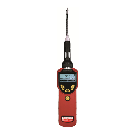
- Page 1 Handheld PID Monitors...
-
Page 2: Table Of Contents
CONTENTS Chapter 1 - Introduction Product registration Standards and certifications Safety Read before operating Proper Product Disposal At End Of Life Standard package contents Chapter 2 - General information Key features Physical description Chapter 3 - Charging the battery Charging a spare rechargeable battery Replacing rechargeable Li-Ion battery Low voltage warning Clock battery... - Page 3 Pump status Calibration status Bump status Glance mode Enter glance mode Glance mode screens Exit glance mode Reverse direction navigation Policy enforcement Setting policy enforcement Chapter 7 - Operating modes MiniRAE 3000+ & ppbRAE 3000+ Basic user level/hygiene mode UltraRAE 3000+ Chapter 8 - UltraRAE 3000+ operation Compound-specific measurement Measurement phases...
- Page 4 Datalogging Datalogging event Datalogging sample Auto/manual/snapshot datalogging Chapter 11 - Standard kit & accessories Accessories AC adapter (battery charger) Alkaline battery adapter External filter Optional accessories Calibration adapter Calibration regulator Organic vapor zeroing kit AutoRAE 2 automatic test & calibration system Chapter 12 - Calibration Standard two-point calibration Entering calibration...
- Page 5 Datalog Monitor setup Chapter 16 - Hygene mode Basic user level & hygiene mode Entering search mode from hygiene mode Chapter 17 - Advanced user level Advanced user level & hygiene mode Basic user level & search mode Advanced user level & search mode Chapter 18 - Diagnostic mode Entering diagnostic mode Adjusting the pump stall threshold...
- Page 6 MiniRAE 3000+ specifications ppbRAE 3000+ specifications UltraRAE 3000+ specifications Chapter 22 - Troubleshooting Handheld PID Monitors User Manual...
-
Page 7: Chapter 1 - Introduction
By registering your product, you can: Receive notification of product upgrades or enhancements Be alerted to Training classes in your area Take advantage of Honeywell special offers and promotions Standards and certifications Intrinsic Safety US and Canada: Class I, Division 1, Groups A,B,C,D... - Page 8 Wireless Approval For UAE In Middle East TRA REGISTERED No: ER36153/14 or ER36153/15 DEALER No.: HONEYWELL INTERNATIONAL MIDDLE EAST – LTD – DUBAI BR Wireless Approval For QATAR In Middle East ictQATAR Type Approval Reg. No.: R-4466 or R-4635...
-
Page 9: Safety
Safety WARNING This Manual must be carefully read by all individuals who have or will have the responsibility of using, maintaining, or servicing this product. The product will perform as designed only if it is used, maintained, and serviced in accordance with the manufacturer’s instructions. -
Page 10: Read Before Operating
Read and understand instruction manual completely before operating or servicing. USE ONLY RAE SYSTEMS BY HONEYWELL BATTERY PACKS, PART NUMBERS 059- 3051-000, 059-3052-000, AND 059-3054-000. THIS INSTRUMENT HAS NOT BEEN TESTED IN AN EXPLOSIVE GAS/AIR ATMOSPHERE HAVING AN OXYGEN CONCENTRATION GREATER THAN 21%. -
Page 11: Proper Product Disposal At End Of Life
Ne pas melanger les anciennes et les nouvelles batteries, ou bien encore les batteries de differents fabriquants. La calibration de toute instruments de Honeywell doivent être testé en exposant l’instrument a une concentration de gaz connue par une procédure diétalonnage avant de mettre en service l’instrument pour la première fois. - Page 12 CAUTION This device complies with Part 15 of the FCC Rules / Industry Canada license-exempt RSS standard(s). Operation is subject to the following two conditions: (1) this device may not cause harmful interference, and (2) this device must accept any interference received, including interference that may cause undesired operation.
- Page 13 Calibration intervals and bump test procedures may vary due to national legislation. Honeywell recommends using calibration gas cylinders containing the gas that is appropriate to the sensor you are using, and in the correct concentration. Special Notes...
-
Page 14: Standard Package Contents
Standard package contents Instrument Calibration Kit Charging cradle AC/DC Adapter Alkaline Battery Adapter Data Cable Quick Start Guide Handheld PID Monitors User Manual... -
Page 15: Chapter 2 - General Information
CHAPTER GENERAL INFORMATION The compact instrument is designed as a broadband VOC gas monitor and datalogger for work in hazardous environments. It monitors Volatile Organic Compounds (VOC) using a photoionization detector (PID) with a 9.8 eV, 10.6 eV, or 11.7eV gas-discharge lamp. The instrument consists of a PID with associated microcomputer and electronic circuit. -
Page 16: Physical Description
Physical description The main components of the portable VOC monitoring instrument include: Three keys for user interaction with the instrument: 3 operation/programming keys for normal operation or programming LCD display with back light for direct readout and calculated measurements Built-in flashlight for illuminating testing points in dark environments Buzzer and red LEDs for alarm signaling whenever exposures exceed preset limits Charge contacts for plugging directly to its charging station Gas entry and exit ports... -
Page 17: Chapter 3 - Charging The Battery
CHAPTER CHARGING THE BATTERY Always fully charge the battery before using the instrument. The instrument’s Li-ion battery is charged by attaching the instrument to the Travel Charger (or by placing the instrument in the optional Charging cradle). Contacts on the bottom of the instrument meet the Travel Charger’s (or Charging cradle’s) contacts, transferring power without other connections. - Page 18 Try changing the battery and make sure the contacts on the instrument are meeting the Travel Charger’s (or Charging cradle’s) contacts. If the message is still shown, consult your distributor or Honeywell Technical Services. WARNING To reduce the risk of ignition of hazardous atmospheres, recharge and replace batteries only in areas known to be non-hazardous.
-
Page 19: Charging A Spare Rechargeable Battery
Release the battery from the Charging cradle by pulling it back toward the rear of the Charging cradle and tilting it out of its slot. Note: If you need to replace the Li-ion battery pack, replacements are available from Honeywell. The part number is 059-3051-000. -
Page 20: Clock Battery
Li-ion battery or alkaline batteries are removed. This backup battery should last approximately five years and must be replaced by an authorized Honeywell service technician. It is not user-replaceable. WARNING To reduce the risk of ignition of hazardous atmospheres, recharge battery only in area known to be non-hazardous. -
Page 21: Chapter 4 - Basic Operation
CHAPTER BASIC OPERATION Turning the instrument on 1. With the instrument turned off, press and hold [MODE]. 2. When the display turns on, release the [MODE] key. The instrument is now operating and performs self-tests. Once the self-tests are complete, the display shows a graph or numerical gas reading. -
Page 22: Chapter 5 - User Interface
CHAPTER USER INTERFACE The instrument’s user interface consists of the display, LEDs, an alarm transducer, and four keys. The keys are: MODE Flashlight on/off The LCD display provides visual feedback that includes the reading, time, battery condition, and other functions. Item Item Display... - Page 23 Three panes along the bottom of the display are “mapped” to the keys. These change as menus change, but at all times the left pane corresponds to the [Y/+] key, the center pane corresponds to the [MODE] key, and the right pane corresponds to the [N/-] key. Here are three examples of different menus with the relationships of the keys clearly shown: MiniRAE 3000+, ppbRAE 3000+, UltraRAE 3000+ Relationship of buttons to control functions...
-
Page 24: Display
Display The display shows the following information: Item Description Reading Concentration of gas as measured by the instrument Gas info Tells the Correction Factor and type of calibration gas Y/+ key Y/+ key’s function for this screen MODE key MODE key’s function for this screen N/- key N/- key’s function for this screen Pump... - Page 25 If the instrument is equipped with BLE instead of other wireless, the BLE Status icon is shown: Item Reading Gas info Y/+ key MODE key N/- key Pump Datalog Battery BLE status Calibration or bump needed Handheld PID Monitors User Manual...
-
Page 26: Icons
Icons These are the icons shown on the display to indicate functions or status. The instrument has been bump tested and calibrated in compliance with the policy settings. Battery level Charging error Calibration required Bump test required Datalog on Radio Power (Bluetooth or Mesh) Radio signal Pump operational Pump blocked or stalled... -
Page 27: Chapter 6 - Operating The Instrument
Note: The main display may show ppb or ppm and other features, depending on the instrument. The Honeywell logo should appear first. (If the logo does not appear, there is likely a problem and you should contact your distributor or Honeywell RAE Systems Technical Support.) The instrument is now operating and performs self-tests. -
Page 28: Auto-Zero At Startup
Auto-zero at startup Using Honeywell Safety Suite Device Configurator (SSDC), the instrument can be programmed to automatically perform a zero calibration after self-testing during startup. Note: The option is disabled by default. If it is disabled, the instrument performs its self-test and then goes directly to reading mode. -
Page 29: Pump Status
Pump status IMPORTANT! During operation, make sure the probe inlet and the gas outlet are free of obstructions. Obstructions can cause premature wear on the pump, false readings, or pump stalling. During normal operation, the pump icon alternately shows inflow and outflow as shown here: During duty cycling (PID lamp cleaning), the display shows these icons in alternation: If there is a pump failure or obstruction that disrupts the pump, you will see this icon blinking on and off:... -
Page 30: Bump Status
Glance Mode. If you see the message “GLANCE MODE DISABLED,” you must configure the instrument to use Glance Mode. If Glance Mode is enabled, the first screen, with the Honeywell Logo, is displayed. Release the [MODE] and [N/-] keys, and the first screen with information about the instrument is shown. -
Page 31: Glance Mode Screens
Glance mode screens Every screen displayed in sequence as configuration. Press [N/-] to advance to the next screen. If the Wireless modem is turned off, the screen shows “Disabled”. Otherwise, the type of wireless is shown. When the last screen is shown, pressing [N/-] “loops” to the first screen. Exit glance mode The instrument exits Glance Mode and turns off when you press the [MODE] key. -
Page 32: Reverse Direction Navigation
Reverse direction navigation Sometimes you want to go back to a previous screen rather than advance through an entire set of screens before “wrapping around” to that screen again. To reverse direction: 1. Press and hold [N/-] for 3 seconds. 2. -
Page 33: Setting Policy Enforcement
Setting policy enforcement You must use Safety Suite Device Configurator (SSDC) to make changes to Policy Enforcement settings. You must use an AutoRAE 2 Cradle, a Travel Charger, or a Charging cradle. Policy violations are captured in the datalog. Using the travel charger, Charging cradle, or AutoRAE 2 automatic test and calibration system To program an instrument via an AutoRAE 2, you need Safety Suite Device Configurator (SSDC), the AutoRAE 2 connected to a power source, and a USB PC communications cable. - Page 34 7. Click on the serial number of the device to open its characteristics. 8. Click on “Settings” and scroll down to “Policy Settings” 9. Policy Enable Bump” and “Policy Enable Calibration” can be enabled or disabled from this screen. “Policy Bypass Bump” and “Policy Bypass Calibration” can also be activated or deactivated from this screen.
- Page 35 If “Can’t Bypass” is selected, the display looks like this, and only allows the options of performing the test or shutting down: 10. Once you have made your selections in Safety Suite Device Configurator (SSDC), you must upload the changes to the instrument. Click on and the changes will be applied to the equipment.”...
-
Page 36: Chapter 7 - Operating Modes
CHAPTER OPERATING MODES MiniRAE 3000+ & ppbRAE 3000+ Your instrument operates in different modes, depending on the model and its factory default settings. In some cases, you can change modes using a password and the instrument’s navigation. In other cases, you must use Safety Suite Device Configurator (SSDC) software. The default setting for your instrument is: User Level: Basic Operation Mode: Hygiene... -
Page 37: Basic User Level/Hygiene Mode
Basic user level/hygiene mode Default Settings – MiniRAE 3000+ & ppbRAE 3000+ The instrument is programmed to operate in Basic User Level/Hygiene Mode as its default. This gives you the most commonly needed features while requiring the fewest parameter adjustments. Pressing [N/-] steps you from one screen to the next, and eventually return to the main display. -
Page 38: Ultrarae 3000
UltraRAE 3000+ The UltraRAE is actually two monitors in one: Compound-specific monitor VOC monitor As a compound-specific monitor, it takes timed measurements and uses a separation tube in conjunction with software that enables the UltraRAE 3000+ to give specific readings on one particular type of compound, such as benzene or butadiene. - Page 39 The default setting for your instrument is: User Level: Basic Operation Mode: Hygiene See "Hygene mode" on page 93 for more information.. The other options, covered later in this guide, are: User Level: Advanced See "Advanced user level" on page 95 for more information.) Operation Mode: Hygiene User Level: Advanced (See "Advanced user level"...
-
Page 40: Chapter 8 - Ultrarae 3000+ Operation
CHAPTER ULTRARAE 3000+ OPERATION Compound-specific measurement The UltraRAE 3000+ can perform compound-specific measurement in addition to general VOC measurement. This requires using a RAE-Sep separation tube (butadiene or benzene) and having the UltraRAE 3000+ in Tube Mode, operating with a 9.8eV lamp. Measurement phases To perform a compound-specific measurement, follow this order: 1. - Page 41 To begin measuring, turn on the UltraRAE 3000+. This screen is shown, which includes the CF (correction factor) and measurement gas type for calibration reference: Press [N/-] to advance. You will see this screen: WARNING Do not begin sampling yet! Before you start sampling, you must insert a RAE-Sep separation tube into the inlet/holder.
-
Page 42: Separation Tube Preparation
Keep away from children. RAE-Sep tubes should be disposed of according to local regulations. See footnotes of data sheets for disposal information. Only use Honeywell RAE Systems tubes. Handle tubes with care. Tube ends are sharp after ends are broken off. -
Page 43: Inserting The Separation Tube
Inserting the separation tube 1. Unscrew the front of the sampling probe from the base. 2. Slip the tube into the rubber holder in the front portion. Make sure the arrow on the side of the tube points toward the instrument. Insert the other end of the tube into the middle of the base while turning the front portion to tighten it onto the base’s threads. -
Page 44: Measuring
Measuring Once the tube is in place, begin measuring by pressing [Y/+]. The display shows a countdown (60 seconds is shown here, but sampling time depends on the type of separation tube selected and the temperature): Note: You can abort the sampling by pressing [N/-] at any time. Once the countdown is complete, the reading is shown: Press [Y/+] to continue sampling with the tube for 15 minutes to establish a STEL reading, or press [N/-] to return to the main menu. - Page 45 If you press [N/-] to return to the main menu, which shows the tube type instead of the CF (correction factor): Press [N/-] to advance to this screen: If you press [Y/+], you are asked, “Clear peak value! Are You Sure?” to confirm: Press [Y/+] to clear the Peak value and exit to VOC operation.
- Page 46 After a few seconds, the UltraRAE 3000+ enters VOC mode and shows this display: You can step through the rest of the steps by pressing [N/-] repeatedly until you reach the main menu again. Handheld PID Monitors User Manual...
-
Page 47: Chapter 9 - Voc Operation - Ultrarae3000
CHAPTER VOC OPERATION - ULTRARAE3000+ Basic user level/hygiene mode (Default settings) The instrument is programmed to operate in Basic User Level/Hygiene Mode as its default. This gives you the most commonly needed features while requiring the fewest parameter adjustments. Pressing [N/-] steps you from one screen to the next, and eventually return to the main display. If you do not press a key within 60 seconds after entering a display, the instrument reverts to its main display. -
Page 48: Basic Operation - Minirae 3000
Basic operation – MiniRAE 3000+ The instrument is programmed to give you the most commonly needed information quickly. Pressing [N/-] steps you from one screen to the next, and eventually return to the main display. If you do not press a key within 60 seconds after entering a display, the instrument reverts to its main display. -
Page 49: Chapter 10 - Alarm Signals
CHAPTER ALARM SIGNALS During each measurement period, the gas concentration is compared with the programmed alarm limits (gas concentration alarm limit settings). If the concentration exceeds any of the preset limits, the loud buzzer and red flashing LED are activated immediately to warn you of the alarm condition. -
Page 50: Preset Alarm Limits & Calibration
Preset alarm limits & calibration The instrument is factory calibrated with standard calibration gas and is programmed with default alarm limits. These settings can be changed in Programming Mode to align more precisely with your standards. MiniRAE Lite+ Cal Gas (Isobutylene) Cal Span Unit High... -
Page 51: Integrated Sampling Pump
Integrated sampling pump The instrument includes an integrated sampling pump. This diaphragm-type pump that provides a 450 to 550 cc per minute flow rate. Connecting a Teflon or metal tubing with 1/8" inside diameter to the gas inlet port of the instrument, this pump can pull in air samples from 100' (30 m) horizontally or vertically. -
Page 52: Auto/Manual/Snapshot Datalogging
Auto/manual/snapshot datalogging The instrument has three datalog types: Auto Default mode. Collects datalog information when the instrument is sampling. Datalogging occurs only when the instrument’s datalogging is manually started (See "Manual datalog" on Manual page 84 for more information.) Datalogs only during snapshot (single-event capture, initiated by pressing [MODE]) sampling. See "Snapshot Snapshot datalog"... -
Page 53: Chapter 11 - Standard Kit & Accessories
CHAPTER STANDARD KIT & ACCESSORIES Accessories MiniRAE Lite+ The following accessories are included with the instrument: 10.6 eV lamp Flex-I-Probe External filter Green rubber boot Alkaline battery adapter Lamp cleaning kit Tool Kit Lithium-Ion (Li-Ion) battery, if specified Travel Charger, if specified Universal wall adapter, if specified Quick Reference Guide Soft leather carrying case... - Page 54 UltraRAE 3000+ Note: These include the tube as ordered (either benzene or butadiene) The following accessories are included with the instrument: AC Adapter (Battery Charger) Travel Charger Alkaline battery adapter External Filter Hard-case kits also include these accessories: Calibration gas, if specified Calibration adapter Calibration regulator and flow controller Charging cradle (instead of Travel Charger)
-
Page 55: Ac Adapter (Battery Charger)
AC adapter (battery charger) WARNING To reduce the risk of ignition of hazardous atmospheres, recharge battery only in area known to be non-hazardous. Remove and replace battery only in area known to be non-hazardous. Ne charger les batteries que dans emplacements designés non-dangereuses. A battery charging circuit is built into the instrument Charging cradle. -
Page 56: Alkaline Battery Adapter
Alkaline battery adapter WARNING To reduce the risk of ignition of hazardous atmospheres, recharge the battery only in areas known to be non-hazardous. Remove and replace the battery only in areas known to be non-hazardous. An alkaline battery adapter is supplied with each instrument. The adapter (part number 059- 3052-000) accepts four AA alkaline batteries (use only Duracell MN1500) and provides approximately 12 hours of operation. -
Page 57: External Filter
IMPORTANT! Alkaline batteries cannot be recharged. The instrument’s internal circuit detects alkaline batteries and will not allow recharging. If you place the instrument in its Charging cradle, the alkaline battery will not be recharged. The internal charging circuit is designed to prevent damage to alkaline batteries and the charging circuit when alkaline batteries are installed inside the instrument. -
Page 58: Optional Accessories
Optional accessories Calibration adapter The calibration adapter for the instrument is a simple 6-inch Tygon tubing. During calibration, simply insert thetubing into the regular gas inlet probe of the instrument and to the gas regulator on the gas bottle. Calibration regulator The Calibration Regulator is used in the calibration process. -
Page 59: Chapter 12 - Calibration
CHAPTER CALIBRATION Standard two-point calibration Standard Two-Point Calibration (Zero & Span) The following diagram shows the instrument’s calibrations in Basic/Hygiene mode. Note: Dashed line indicates automatic progression. Handheld PID Monitors User Manual... -
Page 60: Entering Calibration
Entering calibration 1. Press and hold [MODE] and [N/-] until you see the Password screen. 2. In Basic User Level, you do not need a password to perform calibrations. Instead of inputting a password, enter calibration by pressing [MODE]. Note: If you inadvertently press [Y/+] and change any of the numbers, simply press [MODE] and you will be directed to the calibration menu. -
Page 61: Zero (Fresh Air) Calibration
Zero (Fresh Air) Calibration This procedure determines the zero point of the sensor calibration curve. To perform a fresh air calibration, use the calibration adapter to connect the instrument to a “fresh” air source such as from a cylinder or Tedlar bag (optional accessory). The “fresh” air is clean, dry air without organic impurities and an oxygen value of 20.9%. -
Page 62: Span Calibration
Reflex PID Technology™ All handheld PID monitors after firmware version 2.20 benefit from our patented Reflex PID Technology™. It provides several benefits, including enhanced stability and accuracy, particularly at very low levels. One time each hour, Reflex PID™ Technology adjusts the zero point automatically to ensure greater uniformity in readings, especially when detecting ultra- low levels (ppb range) of VOCs. -
Page 63: Exiting Two-Point Calibration In Basic User Level
If you have pressed [Y/+] to enter Span calibration, then you will see the name of your Span gas (the default is isobutylene) and the span value in parts per million (ppm). You will also see this message that prompts you: ppbRAE 3000+ MiniRAE 3000+, UltraRAE 3000+, MiniRAE Lite+ Note: The default Span value is 100ppm on MiniRAE 3000+ and UltraRAE 3000+, only ppbRAE... -
Page 64: Three-Point Calibration
CHAPTER Three-point calibration For enhanced accuracy, it is possible to perform a second Span calibration in addition to the Zero and Span calibrations outlined in the previous section. Your instrument first must be set to allow this third calibration. This requires using Safety Suite Device Configurator (SSDC) software and a PC, as well as a higher concentration of calibration gas. -
Page 65: Span 2 Calibration
Span 2 calibration The minimum value of Span 2 gas should be 1000 ppm. If the primary concern is accuracy at low concentration, only using the 2-point calibration process with Span 1 set to 100 ppm is adequate. The reading error at 10 ppm will be lower. If Span 1 is set to 10 ppm, the reading error under 100 ppm (or over 100ppm to 1000 ppm) will be higher. -
Page 66: Exiting Three-Point Calibration
When Span calibration is complete, you will see a message similar to this (the value shown here is for example only): Span 2 is done! Reading = 1000 ppm The instrument then exits Span calibration and shows the Zero calibration menu on its display. Note: The reading should be very close to the span gas value. -
Page 67: Chapter 14 - Bump Test
CHAPTER BUMP TEST Honeywell recommends that a bump test be conducted prior to each day’s use. The purpose of a bump test is to ensure that the instrument’s sensors respond to gas and all the alarms are enabled and functional. -
Page 68: Chapter 15 - Programming Mode
CHAPTER PROGRAMMING MODE On the MiniRAE 3000+, ppbRAE 3000+, or UltraRAE 3000+, Programming Mode can be entered from either Hygiene Mode or Search Mode. If the current user mode is Basic, you must provide a 4-digit password to enter. The MiniRAE Lite+ has only Search mode. Manual datalog When the instrument is set to Manual Datalog, you turn datalogging on and off by stepping through the displays from the Main Display, and then pressing the keys to select datalog on/off... -
Page 69: Entering Programming Mode
Entering programming mode Note: The default password is 0000. 1. Press and hold [MODE] and [N/-] until you see the Password screen. 2. Input the 4-digit password: Increase the number from 0 through 9 by pressing [Y/+]. Step from digit to digit using [N/-]. Press [MODE] when you are done. - Page 70 MiniRAE 3000+, ppbRAE 3000+, UltraRAE 3000+ MiniRAE Lite+ Note: When you reach Monitor Setup and press [N/-], the menu cycles back to Calibration. Handheld PID Monitors User Manual...
-
Page 71: Programming Mode Menus
Programming mode menus The Programming Mode allows anyone with the password to change the instrument’s settings, calibrate the instrument, modify the sensor configuration, enter user information, etc. Programming Mode has five menus. Each menu includes several sub-menus to perform additional programming functions. The table on the next shows the menus and sub-menus. -
Page 72: Exiting Programming Mode
Mesh Channel* Mesh Interval* LCD Contrast* Once you enter Programming Mode, the LCD displays the first menu, Calibration. Each subsequent menu is accessed by pressing [N/ ] repeatedly until the desired menu is displayed. To enter a sub-menu of a menu, press [Y/+]. Exiting programming mode To exit Programming Mode and return to normal operation, press [MODE] once at any of the programming menu displays. -
Page 73: Reverse Direction - Menu Selection
Reverse direction – menu selection Lists can be long, so rather than progressing in one direction through every item in the list before “looping” back to the first item, you can change the scrolling direction. To reverse direction: Press and hold [N/-] for 5 seconds. The direction arrow changes. Now when you press [N/-], the menu items are scrolled through in the other direction. - Page 74 Bump test For the procedure for performing a bump test See "Bump test" on page 67 for more information. A bump test can be performed either manually or using the AutoRAE 2 Automatic Test and Calibration System. When a bump test is done manually, the instrument makes a pass/fail decision based on sensor performance, but the user still has the responsibility to make sure all the alarms are enabled and functional.
-
Page 75: Measurement
Measurement The sub-menus for Measurement are Measurement Gas and Measurement Unit. Measurement gases Note: This feature is not available in the MiniRAE Lite+ Measurement gases are organized in four lists: My List is a customized list of gases that you create. It contains a maximum of 10 gases and can only be built in Safety Suite Device Configurator (SSDC) on a PC and transferred to the instrument. - Page 76 CFs of VOCs relative to real-time calibration gas were calculated based on the CFs of the VOCs relative to isobutylene, using the formula CF = CF1 /CF2, where CF1 is the measurement gas CF relative to isobutylene and CF2 is calibration gas CF relative to isobutylene, CF is the final value included in the “Custom Gas”...
- Page 77 Tube selection (UltraRAE 3000+ only) When operating the UltraRAE 3000+ in Compound Specific mode, the internal computer works most effectively when it is told which type of separation tube is being used. 1. Scroll through the menu by pressing [N/-]. 2.
- Page 78 Alarm setting During each measurement period, the gas concentration is compared with the programmed alarm limits (gas concentration alarm limit settings: Low, High, TWA and STEL). If the concentration exceeds any of the preset limits, the loud buzzer and red flashing LED are activated immediately to warn of the alarm condition.
- Page 79 High alarm You can change the High Alarm limit value. The value is typically set by the instrument to match the value for the current calibration gas. It is expressed in parts per billion (ppb). Note: The default value depends on the measurement gas. To change the High Alarm value: 1.
- Page 80 STEL alarm Note: This feature is not included on MiniRAE Lite+. You can change the STEL Alarm limit value. The value is typically set by the instrument to match the value for the calibration gas. It is expressed in parts per billion (ppb). Note: The default value depends on the measurement gas.
- Page 81 Alarm mode There are two selectable alarm types: Latched When the alarm is triggered, you can manually stop the alarm. The latched setting only controls alarms for High Alarm, Low Alarm, STEL Alarm, and TWA alarm. Note: To clear an alarm when the instrument is set to “Latched,” press [Y/+] when the main (Reading) display is shown.
-
Page 82: Datalog
Datalog The instrument calculates and stores the concentration and ID of each sample taken. In the datalog sub-menu, a user can perform the tasks and functions shown below. MiniRAE 3000+, ppbRAE 3000+, UltraRAE MiniRAE Lite+ 1. Scroll through the Datalog sub-menu using the [N/-] key until the display shows the desired parameter to be changed: Clear Datalog Interval... - Page 83 Interval Intervals are shown in seconds. The default value is 60 seconds. The maximum interval is 3600 seconds. 1. Press [Y/+] to increase each digit’s value. 2. Press [N/-] to advance to the next digit. 3. Again, use [Y/+] to increase the number. Repeat this process until all numbers are entered.
- Page 84 Datalog type The instrument has three datalog types: Auto Default mode. Collects datalog information when the instrument is sampling. Manual Datalogging occurs only when the instrument’s datalogging is manually started (see below for details). Snapshot Datalogs only during single-event capture sampling. Note: You can only choose one datalog type to be active at a time.
-
Page 85: Monitor Setup
Monitor setup Many settings can be accessed in this menu, including setting the date and time and adjusting the pump’s on/off duty cycle. MiniRAE 3000+, ppbRAE 3000+, UltraRAE 3000+ MiniRAE Lite+ Radio power The radio connection can be turned on or off. (The default value is off.) 1. - Page 86 Site ID Enter an 8-digit alphanumeric/character Site ID in the programming mode. This Site ID is included in the datalog report. 1. Press [Y/+] and the display shows the current site ID. Example: “RAE00001.” Note that the left-most digit flashes to indicate it is the selected one. 2.
- Page 87 User mode Note: This feature is not included on MiniRAE Lite+. The instrument has two user modes: Basic Basic users can only see and use a basic set of functions. Advanced Advanced users can see all screens and perform all available functions. Note: The default value for User Mode is Basic.
- Page 88 Duty cycle The pump’s duty cycle is the ratio of its on time to off time. The duty cycle ranges from 50% to 100% (always on). Duty cycling is employed by the instrument to clean the PID. A lower duty cycle has a greater effect on keeping the PID clean than a higher duty cycle.
- Page 89 Language English is the default language, but other languages can be selected for the instrument. 1. Press [N/-] to step from one option to the next. 2. Press [Y/+] to make your selection (the dark circle in the “radio button” indicates “on”). 3.
- Page 90 Unit ID This three-digit number keeps data separated by instrument when more than one instrument is used in a network. If multiple sensing units are attempting to communicate with the same Host, then the units must all have a different Unit ID. 1.
- Page 91 Lamp ID The instrument does not automatically identify the type of lamp installed. If the lamp type is replaced with a different UV Lamp energy, you must select the lamp type. 1. Scroll through the menu by pressing [N/-]. 2. Press [Y/+] to make a selection. 3.
- Page 92 Mesh interval Set the time interval at which the instrument’s mesh radio sends out a signal. This can range from once every 10 seconds to once every four minutes (240 seconds). The transmission frequency is user-adjustable, but a rate of at least once every 30 seconds is recommended. Note: Shorter intervals reduce battery life.
-
Page 93: Chapter 16 - Hygene Mode
CHAPTER HYGENE MODE Note: This feature is not included on MiniRAE Lite+. The instrument usually operates in Hygiene Mode, which provides basic functionality. However, it is possible to operate it in a second mode called Search Mode. Here are the primary differences: Hygiene Automatic measurements, continuously running and datalogging, and calculates additional exposure... -
Page 94: Entering Search Mode From Hygiene Mode
Entering search mode from hygiene mode In order to change the instrument’s operational mode from Hygiene Mode to Search Mode, you must enter the password-protected Programming Mode: 1. Hold [MODE] and [N/-] until you see the password screen. 2. Use [Y/+] to increment to the number you want for the first digit. (If you pass by the desired number, press [Y/+] until it cycles through to 0 again. -
Page 95: Chapter 17 - Advanced User Level
CHAPTER ADVANCED USER LEVEL The User Mode called Advanced User Level allows a greater number of parameters to be changed than Basic User Level. It can be used with either of the Operation Modes, Hygiene Mode or Search Mode. Advanced user level & hygiene mode With the instrument in Operation Mode: Hygiene Mode, enter User Mode: Advanced User Level (refer to the section called Monitor Mode for instructions). -
Page 96: Basic User Level & Search Mode
Basic user level & search mode With the instrument in Operation Mode in MiniRAE Lite+: Search Mode, enter User Mode and select Basic User Level (refer to the section called User Mode for instructions). When the instrument is in Search Mode, it only samples when you activate sampling. When you see the display that says, “Ready…Start sampling?”... -
Page 97: Advanced User Level & Search Mode
Advanced user level & search mode With the instrument in Operation Mode: Search Mode, enter User Mode and select Advanced User Level (refer to the section called Monitor Mode for instructions). Operation is similar to Basic User Level & Sampling Mode, but now allows you to change calibration and measurement reference gases. -
Page 98: Chapter 18 - Diagnostic Mode
CHAPTER DIAGNOSTIC MODE IMPORTANT! Diagnostic Mode is designed for servicing and manufacturing, and therefore is not intended for everyday use, even by advanced users. It provides raw data from sensors and about settings, but only allows adjustment of pump stall parameters, which should only be changed by qualified personnel. -
Page 99: Adjusting The Pump Stall Threshold
Adjusting the pump stall threshold If the gas inlet is blocked but the pump does not shut down, or the pump shuts down too easily with a slight blockage, the pump stall threshold value may be set too high or too low. Use the following steps to adjust the pump stall threshold: Pump High 1. -
Page 100: Testing The Humidity Sensor
Testing the humidity sensor 1. Press [MODE] to step through the diagnostic screens until you reach a screen that says “THP” (for “temperature, humidity, pressure,” although pressure is not supported) at the top. There are three numbers for the humidity reading (“H”). The first number is the current humidity reading from the sensor. -
Page 101: Exiting Diagnostic Mode
Exiting diagnostic mode You can exit Diagnostic Mode and go directly to Programming Mode or Monitor Mode as outlined above, or you can exit Diagnostic Mode completely. To exit Diagnostic Mode so that it cannot be re-entered without a restart: Shut down the instrument. -
Page 102: Chapter 19 - Transferring Data
CHAPTER TRANSFERRING DATA Transferring data to & from a computer Once you have connected your instrument Charging cradle, travel charger or AutoRAE 2 to the PC, you can transfer data, including a download of the datalog to the computer and updates of firmware to the instrument (should this ever be necessary). -
Page 103: Uploading Firmware To The Instrument From A Pc
NOTE: If connected to the Internet, Safety Suite DC or Safety Suite DM provides the latest firmware automatically. If not connected to the internet, click on Update and manually add the latest firmware from Honeywell’s website. - sps.honeywell.com/us/en/software Handheld PID Monitors... -
Page 104: Chapter 20 - Maintenance
CHAPTER MAINTENANCE The major maintenance items of the instrument are: Battery pack PID sensor PID lamp Sampling pump Inlet connectors and filters Note: Maintenance should be performed by qualified personnel only. Note: The printed circuit board of the instrument is connected to the battery pack even if the power is turned off. -
Page 105: Replacing The Li-Ion Battery
Replacing the Li-ion battery 1. Turn off the instrument. 2. Located on the rear of the instrument is a battery tab. Slide it down to unlock the battery. 3. Remove the battery pack from the battery compartment by tilting it out. 4. -
Page 106: Replacing The Alkaline Battery Adapter
Replacing the alkaline battery adapter An alkaline battery adapter is supplied with each instrument. The adapter (part number 059- 3052-000) accepts four AA alkaline batteries (use only Duracell MN1500) and provides approximately 12 hours of operation. The adapter is intended to be used in emergency situations when there is no time to charge the Li-ion battery pack. -
Page 107: Pid Sensor & Lamp Cleaning/Replacement
PID sensor & lamp cleaning/replacement Sensor Components – MiniRAE 3000+, ppbRAE 3000+ The sensor module is made of several components and is attached to the lamp-housing unit as shown below. Note: Most of the items listed below are service restricted and can only be purchased by an Authorized service distributor. - Page 108 Sensor Components – UltraRAE 3000+ The sensor module is made of several components and is attached to the lamp-housing unit as shown below. Description Part Number Description Part Number Inlet probe assembly 023-3012-000 7 Sensor module assembly* 023-3005-X00 O-ring, 35mm x 2mm PID sensor 023-3010-001 Porous metal filter...
- Page 109 Sensor Components – MiniRAE Lite+ The sensor module is made of several components and is attached to the lamp-housing unit as shown below. Description Part Number Description Part Number Inlet probe 023-3012-000 Sensor 4GPID C08-0902-002 Sensor cover assembly 023-3009-000-FRU Sensor module assembly 3011-2788-001 Gas plate 3011-2793-001...
-
Page 110: Cleaning The Pid Sensor
Cleaning the PID sensor Place the entire PID sensor module into GC grade methanol. It is highly recommended that an ultrasound bath to be used to clean the sensor for at least 15 minutes. Then dry the sensor thoroughly. Never touch the electrodes of the sensor by hand. Also use a methanol-soaked cotton swab to wipe off the lamp housing where it contacts the sensor when the sensor is installed. -
Page 111: Determining The Lamp Type
Determining the lamp type Note: This feature is not included on the MiniRAE Lite+. The monitor may be able to accommodate three lamp values: 9.8eV, 10.6eV (standard) and 11.7eV. There are two ways to determine the lamp type. 1. Turn off the instrument and remove the lamp. Now look at the serial number. The following identify the lamp type: 10.6eV: SN:106 XXXXXXX 9.8eV: SN:098 XXXXXXX... -
Page 112: Sampling Pump
Special servicing note If the instrument needs to be serviced, contact either: 1. The Honeywell distributor from whom the instrument was purchased; they will return the instrument on your behalf. 2. The Honeywell Technical Service Department. Before returning the instrument for service or repair, obtain a Returned Material Authorization (RMA) number for proper tracking of your equipment. -
Page 113: Chapter 21 - Specifications
CHAPTER SPECIFICATIONS MiniRAE Lite+ specifications Size: 25.5cm x 7.6cm x 6.4cm / 9.25" L x 3.6" W x 2.9" H Weight: 738g /28oz with battery pack Detector: Photoionization sensor with 10.6 eV UV lamp Battery: Rechargeable Lithium-Ion battery pack (snap in, field replaceable) Alkaline battery holder (for 4 AA batteries) Battery Charging: Less than 8 hours to full charge Operating Hours: Non-wireless... - Page 114 Response time (T 2 seconds Accuracy (Isobutylene): 10 to 2000 ppm: ±5% at calibration point. PID Detector: Easy access to lamp and sensor for cleaning and replacement Calibration: Two-point field calibration of zero and standard reference gases Patented Reflex PID™ technology Inlet Probe: Flexible 5"...
- Page 115 MiniRAE 3000+ specifications Size: 25.5cm x 7.6cm x 6.4cm (9.25" L x 3.6" W x 2.9" H) Weight: 738g / 28oz with battery pack Detector: Photoionization sensor with 9.8, 10.6, or 11.7 eV UV lamp Battery: A 3.7V rechargeable Lithium-Ion battery pack (snap in, field replaceable, at non-hazardous location only) Alkaline battery holder (for 4 AA batteries) Battery Less than 8 hours to full charge...
- Page 116 Response time (T 2 seconds Accuracy (Isobutylene): 10 to 2000 ppm: ±3% at calibration point. PID Detector: Easy access to lamp and sensor for cleaning and replacement Correction Factors: Over 200 VOC gases built in Calibration: Two-point field calibration of zero and standard reference gases Patented Reflex PID™...
- Page 117 Humidity: 0% to 95% relative humidity (non-condensing) Housing (including rubber Polycarbonate, splashproof and dustproof boot): Battery can be changed without removing rubber boot. Handheld PID Monitors User Manual...
- Page 118 ppbRAE 3000+ specifications Size: 25.5cm x 7.6cm x 6.4cm (9.25" L x 3.6" W x 2.9" H) Weight: 738g / 28oz with battery pack Detector: Photoionization sensor with 9.8eV or 10.6eV UV lamp Battery: A 3.7V rechargeable Lithium-Ion battery pack (snap in, field replaceable, at non-hazardous location only) Alkaline battery holder (for 4 AA batteries) Battery Less than 8 hours to full charge...
- Page 119 Response time (T 2 seconds Accuracy (Isobutylene): 10 to 2000 ppm: ±3% at calibration point. PID Detector: Easy access to lamp and sensor for cleaning and replacement Correction Factors: Over 200 VOC gases built in Calibration: Two-point field calibration of zero and standard reference gases Patented Reflex PID™...
- Page 120 Humidity: 0% to 95% relative humidity (non-condensing) Housing (including rubber Polycarbonate, splashproof and dustproof boot): Battery can be changed without removing rubber boot. Handheld PID Monitors User Manual...
- Page 121 UltraRAE 3000+ specifications Size: 25.5 cm x 7.6 cm x 6.4 cm (10" L x 3" W x 2.5" H) Weight: 26 oz (738 g) with battery pack Detector: Photoionization sensor with 9.8, 10.6, or 11.7eV UV lamp Battery: A 4.2V rechargeable Lithium-Ion battery pack (snap in, field replaceable, at non-hazardous location only) Alkaline battery holder (for 4 AA batteries) Battery Less than 8 hours to full charge...
- Page 122 Response time (T 2 seconds Accuracy (Isobutylene): 3% at calibration point PID Detector: Easy access to lamp and sensor for cleaning and replacement Correction Factors: Over 200 VOC gases built in Calibration: Two-point field calibration of zero and standard reference gases Patented Reflex PID™...
- Page 123 Temperature: -20º C to 50º C (-4º to 122º F) Humidity: 0% to 95% relative humidity (non-condensing) Housing (including Polycarbonate, splashproof and dustproof rubber boot): Battery can be changed without removing rubber boot. Handheld PID Monitors User Manual...
- Page 124 CHAPTER TROUBLESHOOTING Problem Possible Reasons & Solutions Discharged battery. Reasons Cannot turn on power Defective battery. after charging the battery Solutions Charge or replace battery. Call Technical Support toll-free at +1 888-749- Lost password Solutions 8878 Dirty filter. Dirty sensor module. Reasons Excessive moisture and water condensation.
- Page 125 Problem Possible Reasons & Solutions Lamp drive circuit. Reasons Weak or defective PID lamp, defective. “Lamp” message during operation Turn the unit off and back on. Solutions Replace UV lamp Lamp drive circuit. Reasons Weak or defective PID lamp. Sensor defective. "Sen"...
- Page 126 Contact Corporate Headquarters Honeywell 700 Mint St. Charlotte, NC 28202, USA Phone : +1 888 749 8878 rae-callcenter@honeywell.com Worldwide Sales Offices USA/Canada 1.877.723.2878 Europe +800.333.222.44/+41.44.943.4380 Middle East +971.4.450.5852 China +86.10.5885.8788-3000 Asia Pacific +852.2669.0828 User Manual059-4026-000 Language: English Revision C @ 2022Wednesday, February 22, 2023...
Need help?
Do you have a question about the MiniRAE 3000+ and is the answer not in the manual?
Questions and answers