
Related Manuals for Honeywell MagneW 3000 Plus


Summary of Contents for Honeywell MagneW 3000 Plus
- Page 1 MagneW 3000 PLUS Smart Electromagnetic Flowmeter Specification and Application Guide 36-KI-29-02 1/98 T tal Plant ®...
- Page 2 In no event is Honeywell liable to anyone for any indirect, special or consequential damages. The information and specifications in this document are subject to change without notice.
-
Page 3: Table Of Contents
Fluid to be Measured ......................15 Measured Liquid Flow Conditions..................15 Detector Location in Piping ....................16 Clearance for Maintenance....................18 SPECIFICATIONS ........................19 Performance ........................19 Design..........................19 Environmental and Operating Conditions................23 DIMENSIONS25 ORDERING DATA AND SPECIAL INSTRUCTIONS ..............36 1/98 MagneW 3000 PLUS Specification and Application Guide... - Page 4 Size 15-200mm................36-KI-16-25 MagneW 3000 PLUS Remote Converter ............36-KI-16-26 MagneW 3000 PLUS Remote Detector Wafer Type, Size 2.5-200mm ....36-KI-16-29 MagneW 3000 PLUS Remote Detector Flange Type, Size 25-400mm....36-KI-16-30 MagneW 3000 PLUS Remote Detector Wafer Type, Size 2.5-200mm ....36-KI-16-31 MagneW 3000 PLUS Remote Detector Flange Type, Size 25-600mm....
- Page 5 MagneW 3000 PLUS Communications Hierarchy for TPS........5 Figure 7 Overview of MagneW 3000 PLUS Wiring Requirements ........7 Figure 8 Typical Wiring Connections for the MagneW 3000 PLUS Remote and Integral Flowmeters..................9 Figure 9 Cable Length Versus Fluid Conductivity............10 Figure 10 Direct Direction, Automatic Dual Range Transfer Hysteresis......11...
-
Page 7: Introduction
• remote communication with SFC®. with the new range of PLUS converters. converter which can be mounted up to The MagneW 3000 PLUS is part of the 300 meters (984 feet) away, depending TotalPlant® Solution (TPS) system. on the application. -
Page 8: Principle Of Operation
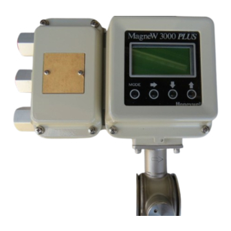
Faraday’s formula: E is proportional to V x B x D Hardware Configuration where: The MagneW 3000 PLUS flowmeter is available as either: E = Induced Electromagnetic • an integral unit—converter mounted on detector, or Voltage • a remote converter/remote detector. -
Page 9: Features
25 to 200 (1 to 7.9) General/submersible Flange 250 to 600 (10 to 23.6) Polyurethane rubber 25 to 200 (1 to 7.9) Chloroprene rubber 250 to 600 (10 to 23.6) CONVERTERS General Integral or remote type 1/98 MagneW 3000 PLUS Specification and Application Guide... -
Page 10: Operator Interface
Auxiliary with Honeywell’s TPS, and through a 0000123456 TOTAL Display 23444 custom field termination assembly (FTA) to Allen-Bradley controllers. Figure 5—Digital Operator Panel Display (configured for % flow range) MagneW 3000 PLUS Specification and Application Guide 1/98... -
Page 11: Diagnostics
Also, through a custom FTA the flowmeter, in the DE mode, can communicate with Allen-Bradley controllers. SFC (Model STS103) MagneW PLUS Integral Model 23445 Remote Model) Figure 6—Typical MagneW 3000 PLUS Communications Hierarchy for TPS 1/98 MagneW 3000 PLUS Specification and Application Guide... -
Page 12: Summary Of Magnew 3000 Plus Features
Summary of MagneW 3000 PLUS Features Table 2 provides a summary of major MagneW 3000 PLUS features and functions. Table 2—Summary of Major MagneW 3000 PLUS Features Feature Function Operating principle based on Faraday’s Law Provides accurate and reliable measurement of process fluid flow rate. -
Page 13: Wiring Summary
8 8 8 8 8 8 8 8 8 8 8 8 8 8 8 8 8 8 8 8 8 8 8 8 Remote Detector Signal cable Power supply Vac or 24 Vdc Pulse output Excitation cable Contact input/output 4 to 20 mA/DE output 23446 Figure 7—Overview of MagneW 3000 PLUS Wiring Requirements 1/98 MagneW 3000 PLUS Specification and Application Guide... -
Page 14: Electrical Connection Considerations
• Do not short the excitation current case. The E terminal and the ground terminals X and Y of the converter. terminal are mutually connected in the unit. MagneW 3000 PLUS Specification and Application Guide 1/98... -
Page 15: Terminal Connections
Terminal symbols X, Y, SB, SA, A, B, C, and E are not indicated because these terminals are not used. 23447 Figure 8—Typical Wiring Connections for the MagneW 3000 PLUS Remote and Integral Flowmeters 1/98 MagneW 3000 PLUS Specification and Application Guide... -
Page 16: Cabling For Remote Detector/Converter
Cabling for Remote Detector/Converter Honeywell offers the excitation and signal cables as a set under a separate model number (Model Number KIW-XXX-XXX). Commercially available cables can be used. The selection of the signal cables depends on certain conditions: • fluid conductivity, •... -
Page 17: Ranging Function
With respect to direct With respect to reverse Adjustable by 0-20% 23449 direction range, direction range, adjustable by 0-20% adjustable by 0-20% 23450 Figure 10—Direct Direction, Automatic Dual Range Transfer Hysteresis Figure 11—Direct/Reverse Transfer Hysteresis 1/98 MagneW 3000 PLUS Specification and Application Guide... -
Page 18: Selection Of Corrosion Resistant Materials
A wide range of uses since it is usable A variety of organic and inorganic acids, Cr : 16% in moderately oxidizing and reducing alkalis, etc. Fe : 5% atmospheres. : 4% Weak to sulfides, sulfuric acid, etc. : Remainder MagneW 3000 PLUS Specification and Application Guide 1/98... -
Page 19: Application Data Worksheet
To use this Honeywell service, please complete the Application Data Sheet and forward it to your Honeywell Representative for submission to Field Instrument Application Engineering. 1/98... -
Page 20: Installation Planning Considerations
Installation Planning Considerations The MagneW 3000 PLUS planning considerations are summarized in Table 5. To ensure proper flowmeter selection and operation, the following installation conditions should be reviewed: • Environmental conditions • Fluid to be measured • Measured liquid flow conditions •... -
Page 21: Fluid To Be Measured
(9.8 to 23.6) 23451 The following liquids may not be successfully measured by MagneW 3000 PLUS , even if their conductance, temperature, and pressure fall within its limits. • Fluids that have sufficient conductivity at high temperatures but not at room temperature, approximately 20°C (68°F). -
Page 22: Detector Location In Piping
Pump Good location 23452 The face-to-face space between the flanges must be sufficient for the given detector size. Never force the detector into an insufficient face-to-face space. 23453 MagneW 3000 PLUS Specification and Application Guide 1/98... - Page 23 2D or greater (minimum 2D if drift current or the like is possible) 23454 The process piping with flanges must be straight and centered. Below are examples of improper alignments. Tilted pipe Off-centered 23455 1/98 MagneW 3000 PLUS Specification and Application Guide...
-
Page 24: Clearance For Maintenance
Suggested minimum clearances are provided below. 500 mm 19.7 in. 400 mm 15.8 in. 400 mm Integral type 15.8 in. 500 mm 19.7 in. 400 mm 15.8 in. 400 mm 15.8 in. Remote detector 23456 MagneW 3000 PLUS Specification and Application Guide 1/98... -
Page 25: Specifications
Specifications Table 6 summarizes pertinent specification data for the MagneW 3000 PLUS . Table 6—Specifications for MagneW 3000 PLUS Performance Accuracy Refer to the following tables. Diameters 2.5 mm to 15 mm (0.1 in. to 0.6 in.): Upper limit value of Vs = set velocity range Accuracy at Vs ≥40%... - Page 26 Table 6—Specifications for MagneW 3000 PLUS , continued Design (continued) Outputs (Transmitter) • Detector’s coil excitation current • Current output without SFC communications requirement: 4 to 20 mA dc into a 0 to 600 ohms load with external 24 Vdc power supply.
- Page 27 Table 6—Specifications for MagneW 3000 PLUS , continued Design (continued) Flange Rating • 25 to 50 mm (1 to 2 in.) diameters: JIS 10K, JIS 16K, JIS 20K, JIS 30K, JPI 150, JPI 300, ANSI 150, ANSI 300, DIN PN10, DIN PN16, DIN PN25, DIN PN40 •...
- Page 28 Table 6—Specifications for MagneW 3000 PLUS , continued Design (continued) Wetted Materials Lining: • 2.5 to 600 mm (0.1 to 23.6 in.) diameters—PFA • 25 to 200 mm (1 to 7.9 in.) diameters—polyurethane rubber • 250 to 600 mm (9.8 to 23.6 in.) diameters—chloroprene rubber...
-
Page 29: Environmental And Operating Conditions
MGG16D, F, U CENELEC EEx de ia II CT4 Remote Detector CE Mark Conformity MagneW 3000 PLUS meets the emission limits for EN 50081-1-1993 and the immunity standards (Europe) for EN 50082-2-1995. 1/98 MagneW 3000 PLUS Specification and Application Guide... -
Page 30: Table 7 Minimum And Maximum Ranges
(0 to 2,023.32) (0 to 202,332.15) 0 to 70.70 0 to 7,070 (19.7) (0 to 2,498.23) (0 to 249,823.32) 0 to 101.79 0 to 10,179 (23.6) (0 to 3,596.81) (0 to 359,681.97) MagneW 3000 PLUS Specification and Application Guide 1/98... -
Page 31: Dimensions25
Dimensions Figures 12 through 20 and Tables 8 through 10 list reference dimensions for the various MagneW 3000 PLUS styles and sizes. Plate Terminal number plate 15.5 millimeters Dimensions: inches FOR REFERENCE ONLY 23671 Figure 12—Wall Mounting Dimensions 1/98 MagneW 3000 PLUS Specification and Application Guide... -
Page 32: Figure 13 2-Inch Pipe Mounting Dimensions
44.3 1.75 50 mm (2-inch) pipe Bracket Material: SPCC (zinc-plated) Bolt Terminal Material: SUS304 number plate 15.5 millimeters Dimensions: inches FOR REFERENCE ONLY 23672 Figure 13—2-inch Pipe Mounting Dimensions MagneW 3000 PLUS Specification and Application Guide 1/98... -
Page 33: Figure 14 Dimensions For Integral Model-Refer To Table 8
Dimensions: inches FOR REFERENCE ONLY øD 23673 Figure 14—Dimensions for Integral Model—Refer to Table 8 1/98 MagneW 3000 PLUS Specification and Application Guide... -
Page 34: Figure 15 Union Joint Dimensions - 2.5 Mm To 15 Mm (0.1 In. To 0.6 In.)
Dimensions: inches FOR REFERENCE ONLY 2.79 2.83 23457 Figure 15—Union Joint Dimensions – 2.5 mm to 15 mm (0.1 in. to 0.6 in.) Sizes MagneW 3000 PLUS Specification and Application Guide 1/98... -
Page 35: Figure 16 Hose Joint Dimensions - 2.5 Mm To 15 Mm (0.1 In. To 0.6 In.)
Dimensions: inches FOR REFERENCE ONLY 2.79 2.83 23458 Figure 16—Hose Joint Dimensions – 2.5 mm to 15 mm (0.1 in. to 0.6 in.) Sizes 1/98 MagneW 3000 PLUS Specification and Application Guide... -
Page 36: Figure 17 Idf/Tri-Clamp Dimensions - 2.5 Mm To 15 Mm (0.1 In. To 0.6 In.)
Dimensions: inches FOR REFERENCE ONLY 2.79 2.83 23459 Figure 17—IDF/Tri-Clamp Dimensions – 2.5 mm to 15 mm (0.1 in. to 0.6 in.) Sizes MagneW 3000 PLUS Specification and Application Guide 1/98... -
Page 37: Figure 18 Wafer Dimensions - 2.5 Mm To 15 Mm (0.1 In. To 0.6 In.) And 25 Mm To
Sizes 25 to 200 mm (1 to 7.9 inches) 23460 Figure 18—Wafer Dimensions – 2.5 mm to 15 mm (0.1 in. to 0.6 in.) and 25mm to 200 mm (1 in. to 7.9 in.) Sizes—Refer to Table 8 1/98 MagneW 3000 PLUS Specification and Application Guide... -
Page 38: Table 8 Dimensions For Figures 14 And 18
(4.9) (5.5) (5.2) (3.7) (10.8) (6.2) (8.4) (7.5) 147 ±3 (5.787 ±0.118) (5.9) (6.3) (6.3) (4.3) (12.5) (9.5) (9.5) (8.7) 195 ±3 (7.677 ±0.118) (7.9) (7.90) (7.3) (5.3) (14.5) (8.3) (11.4) (10.6) MagneW 3000 PLUS Specification and Application Guide 1/98... -
Page 39: Figure 19 Flange Dimensions - 25 Mm (1 In.)
Dimensions: inches FOR REFERENCE ONLY 7.36 Inner diameter: 24 ±0.5 mm (0.944 ±0.019 in.) Weight: 5.5 kg (12.1 lbs.) 23461 Figure 19—Flange Dimensions – 25 mm (1 in.) Sizes 1/98 MagneW 3000 PLUS Specification and Application Guide... -
Page 40: Figure 20 Flange Dimensions - 40 Mm To 140 Mm (1.6 In. To 3.9 In.) And 150 Mm To 600 Mm (5.9 In. To 23.6 In.)-Refer To Table 9
Sizes 150 to 600 mm (5.9 to 23.6 inches) 23462 Figure 20—Flange Dimensions – 40 mm to 100 mm (1.6 in. to 3.9 in.) and 150 mm to 600 mm (5.9 in. to 23.6 in.) Sizes—Refer to Table 9 MagneW 3000 PLUS Specification and Application Guide 1/98... -
Page 41: Table 9 Dimensions For Figure 20
(17.519 ±0.236) (23.6) (13.3) (14.3) (29.5) (14.3) (469.5) 495 ±6 500 (19.7) (19.488 ±0.236) (23.6) (13.5) (15.1) (30.4) (14.5) (445.3) 595 ±6 600 (23.6) (23.425 ±0.236) (25.6) (15.4) (17.6) (34.8) (16.4) (599.6) 1/98 MagneW 3000 PLUS Specification and Application Guide... -
Page 42: Ordering Data And Special Instructions
Ordering Data and Special Instructions Refer to the following model selection guides to build the appropriate model numbers for the MagneW 3000 PLUS components that you need to meet your application requirements. MagneW 3000 PLUS Specification and Application Guide 1/98... -
Page 43: Model Selection Guides
_, _ _ = Stocked KEY NUMBER Selection Availability Description MagneW 3000 PLUS Integral Converter and MGG 18D Wafer Style Detector MGG14ID TABLE I A - Power Supply AC100V 50/60Hz - Refer to Factory for Delivery A _ _ _... - Page 44 2 Outputs (ranging function, warning for contact outputs) Note 3 D - Style Code _ _ _ X None TABLE III A - Version Honeywell Version (indication other than SI units) TABLE IV A - Options Empty Pipe Detection Function Pulse Output (open collector) Traceability Certificate...
- Page 45 36-KI-16-24 Page 3 of 5 Availability MGG14ID TABLE V Selection A - Diameter Flow Range Minimum Flow Range Maximum Millimeter Inches In Litres In Litres In US GPM In US GPM 0.008 0.03 0.779 2.95 002 _ _ _ _ _ _ _ _ _ 0.031 0.12 3.113...
- Page 46 36-KI-16-24 Page 4 of 5 Availability MGG14ID TABLE V (continued) Selection E - Grounding Rings SUS316 _ _ _ _ _ _ _ S _ _ _ _ SS Top Hat Style (Upstream Only) _ _ _ _ _ _ _ G _ _ _ _ Hastelloy C _ _ _ _ _ _ _ C _ _ _ _ (with Teflon PFA only)
- Page 47 36-KI-16-24 Page 5 of 5 Availability MGG14ID TABLE VII Selection Version Standard TABLE VIII Options Calibration Certificate (additional copy) Traceability Certificate Mill Sheet (only for electrodes and grounding rings) Gasket for Plastic Piping Attachment of Tagplate to Detector Terminal Box (Note 4) Attachment of Tagplate to Neck of Detector (Note 4)
-
Page 48: Magnew 3000 Plus Integral Converter And Mgg18F Flange Style Detector
_ _ _ _ _ _ _ _ _ _ _ _ _ , _ = Stocked KEY NUMBER Selection Availability Description MagneW 3000 PLUS Integral Converter and MGG18F Flange Style Detector MGG14IF TABLE I A - Power Supply AC100V 50/60Hz - Refer to Factory for Delivery A _ _ _... - Page 49 2 Outputs (ranging function, warning for contact outputs) Note 3 D - Style Code _ _ _ X None TABLE III A - Version Honeywell Version (indication other than SI units) TABLE IV A - Options Empty Pipe Detection Function Pulse Output (open collector) Traceability Certificate...
- Page 50 36-KI-16-25 Page 3 of 5 Availability MGG14IF TABLE V Selection A - Diameter Flow Range Minimum Flow Range Maximum Millimeter Inches In Litres In Litres In US GPM In US GPM 0.779 2.95 77.931 295.00 025 _ _ _ _ _ _ _ _ _ _ 1.990 7.53 199.011...
- Page 51 36-KI-16-25 Page 4 of 5 Availability MGG14IF TABLE V (continued) Selection D - Electrodes SUS316L _ _ _ _ _ _ _ L _ _ _ _ _ Hastelloy C _ _ _ _ _ _ _ C _ _ _ _ _ (with Teflon PFA only) Titanium _ _ _ _ _ _ _ K _ _ _ _ _...
- Page 52 36-KI-16-25 Page 5 of 5 Availability MGG14IF TABLE VI Selection A - Finish Standard Corrosion-resistant Finish Corrosion-proof Finish TABLE VII Version Standard TABLE VIII Options Calibration Certificate (additional copy) Traceability Certificate Mill Sheet (only for electrodes and grounding rings) Gasket for Plastic Piping Attachment of Tagplate to Detector Terminal Box (Note 4) Attachment of Tagplate to Neck of Detector...
-
Page 53: Magnew 3000 Plus Remote Converter
36-KI-16-26 Issue 3 Page 1 of 3 MagneW 3000 PLUS Remote Converter Model Selection Guide Instructions Select the desired key number. The arrow to the right marks the selection available. Make one selection from Tables I thru III, using the column below the proper arrow. - Page 54 2 Outputs (ranging function, warning for contact outputs) Note 3 D - Style Code _ _ _ X None TABLE III A - Version Honeywell Version (indication other than SI units) TABLE IV A - Options Empty Pipe Detection Function Pulse Output (open collector) Traceability Certificate...
- Page 55 36-KI-16-26 Page 3 of 3 RESTRICTIONS Restrictions Letter Available Only With Not Available With Table Selection Table Selection _ _ 1, _ _ 3 _ _ 1, _ _ 2 F1, F2, F3, F4 F2, F4 F1, F3 Select only one from this group...
- Page 56 _ , _ = Stocked KEY NUMBER Selection Availability Description MagneW 3000 PLUS Remote Detector,Wafer Type, Sizes 2.5-200mm MGG17D CSA FM SP Approved CL I, Div.1, Groups B-G TABLE I A - Diameter Flow Range Minimum Flow Range Maximum Millimeter...
- Page 57 36-KI-16-29 Page 2 of 3 Availability MGG17D TABLE I (Continued) Selection D - Electrodes SUS316L _ _ _ _ _ _ L _ _ _ _ _ Hastelloy C _ _ _ _ _ _ C _ _ _ _ _ (with Teflon PFA only) Titanium _ _ _ _ _ _ K _ _ _ _ _...
- Page 58 36-KI-16-29 Page 3 of 3 Availability MGG17D TABLE II Selection A - Finish Standard Corrosion-resistant Finish Corrosion-proof Finish B - Bolts/Nuts None Carbon Steel SUS304 TABLE III Version Standard TABLE IV Options Calibration Certificate (additional copy) Traceability Certificate Mill Sheet (only for electrodes and grounding rings) Gasket for Plastic Piping Attachment of Tagplate to Detector Terminal Box (Note 1)
- Page 59 _ , _ = Stocked KEY NUMBER Selection Availability Description MagneW 3000 PLUS Remote Detector,Flange Type, Sizes 15-400 MGG17F CSA FM SP Approved CL I, Div. 1, Groups B-G TABLE I A - Diameter Flow Range Minimum Flow Range Maximum...
- Page 60 36-KI-16-30 Page 2 of 3 Availability MGG17F TABLE I (Continued) Selection Flange ANSI 150 (diameter 80mm or larger) SUS304 _ _ _ _ A14 _ _ _ _ _ _ Flange ANSI 300 (diameter 80mm or larger) SUS304 _ _ _ _ A24 _ _ _ _ _ _ Flange JIS G3451 F12 (diameter 80mm or larger) SUS304 _ _ _ _ G14 _ _ _ _ _ _...
- Page 61 36-KI-16-30 Page 3 of 3 Availability MGG17F TABLE II Selection A - Finish Standard Corrosion-resistant Finish Corrosion-proof Finish TABLE III Version Standard TABLE IV Options Calibration Certificate (additional copy) Traceability Certificate Mill Sheet (only for electrodes and grounding rings) Gasket for Plastic Piping Attachment of Tagplate to Detector Terminal Box (Note 1) Attachment of Tagplate to Neck of Detector...
-
Page 62: Magnew 3000 Plus Remote Detector Wafer Type, Size 2.5-200Mm
_ _ _ _ _ _ _ _ _ _ _ _ _ , _ = Stocked KEY NUMBER Selection Availability Description MagneW 3000 PLUS Remote Detector,Wafer Type, Sizes 2.5-200mm MGG18D TABLE I A - Diameter Flow Range Minimum Flow Range Maximum Millimeter Inches... - Page 63 36-KI-16-31 Page 2 of 3 Availability MGG18D TABLE I (continued) Selection D - Electrodes SUS316L _ _ _ _ _ _ L _ _ _ _ _ Hastelloy C _ _ _ _ _ _ C _ _ _ _ _ (with Teflon PFA only) Titanium _ _ _ _ _ _ K _ _ _ _ _...
- Page 64 36-KI-16-31 Page 3 of 3 Availability MGG18D TABLE I (continued) Selection I - Calibration Standard Calibration - 2 Point (0, 100%) w/ Master Converter _ _ _ _ _ _ _ _ _ _ _ R 3 Point (0, 50, 100%) with Master Converter _ _ _ _ _ _ _ _ _ _ _ P 5 Point (0, 25, 50, 75, 100%) with Master Converter _ _ _ _ _ _ _ _ _ _ _ Q...
-
Page 65: Magnew 3000 Plus Remote Detector Flange Type, Size 25-600Mm
- _ _ _ _ _ _ _ _ _ _ _ _ _ _ , _ = Stocked KEY NUMBER Selection Availability Description MagneW 3000 PLUS Remote Detector,Flange Type, Sizes 25-600 MGG18F TABLE I A - Diameter Flow Range Minimum Flow Range Maximum Millimeter Inches In Litres... - Page 66 36-KI-16-32 Page 2 of 3 Availability MGG18F TABLE I (Continued) Selection Flange JIS 10K (diameter 80mm or larger) SUS304 _ _ _ _ J14 _ _ _ _ _ _ Flange JIS 20K (diameter 80mm or larger SUS304 _ _ _ _ J24 _ _ _ _ _ _ Flange JIS 30K (diameter 80mm-200mm) SUS304 _ _ _ _ J34 _ _ _ _ _ _...
- Page 67 36-KI-16-32 Page 3 of 3 Availability MGG18F Selection G - Face to Face Dimension Standard _ _ _ _ _ _ _ _ _ _ A _ _ _ _ _ _ _ _ _ _ _ _ 9 _ _ Competitive (refer to Table 103 and consult factory) H - Installation/Wiring Direction - Remote Only...
- Page 68 _ , _ _ _ _ _ _ _ _ _ _ _ _ KEY NUMBER Selection Availability Description MagneW 3000 PLUS Submersible Detector,Wafer Type, Sizes 15-200mm MGG19D TABLE I A - Diameter Flow Range Minimum Flow Range Maximum Millimeter Inches...
- Page 69 36-KI-16-33 Page 2 of 4 Availability MGG19D TABLE I (continued) Selection D - Electrodes SUS316L _ _ _ _ _ _ L _ _ _ _ _ Hastelloy C _ _ _ _ _ _ C _ _ _ _ _ (with Teflon PFA only) Titanium _ _ _ _ _ _ K _ _ _ _ _...
- Page 70 36-KI-16-33 Page 3 of 4 Availability MGG19D TABLE II Selection A - Finish Standard B - Bolts/Nuts None Carbon Steel SUS304 TABLE III Version Standard TABLE IV Options None Calibration Certificate (additional copy) Traceability Certificate Mill Sheet (only for electrodes and grounding rings) Gasket for Plastic Piping Attachment of Tagplate to Detector Terminal Box (Note 1)
- Page 71 36-KI-16-33 Page 4 of 4 Availability MGG19D TABLE VII (continued) Selection B - Terminals (Detector Side) _ _ _ A _ With Terminals for MGG Type Detector (MG PLUS ) C - Terminals (Converter Side) Without Terminals _ _ _ _ X _ _ _ _ A With Terminals for MGG/KIX/KIC Type Converter Note 1: Must be selected if Tag number is required.
-
Page 72: Magnew 3000 Plus Submersible Remote Detector Flange Type
_ , _ _ _ _ _ _ _ _ _ _ _ _ KEY NUMBER Selection Availability Description MagneW 3000 PLUS Submersible Remote Detector, Flange Type, MGG19F Sizes 25-600mm TABLE I A - Diameter Flow Range Minimum Flow Range Maximum Millimeter... - Page 73 36-KI-16-34 Page 2 of 4 Availability MGG19F TABLE I (Continued) Selection Flange JPI 150 Standard _ _ _ _ P11 _ _ _ _ _ _ Flange JPI 300 Standard _ _ _ _ P21 _ _ _ _ _ _ Flange JIS 10K (diameter 80mm or larger) SUS304 _ _ _ _ J14 _ _ _ _ _ _...
- Page 74 36-KI-16-34 Page 3 of 4 Availability MGG19F Selection G - Face to Face Dimension Standard _ _ _ _ _ _ _ _ _ _ A _ _ _ _ _ _ _ _ _ _ _ _ 9 _ _ Competitive (Refer to Table 103 and Consult Factory) H - Installation/Wiring Direction...
- Page 75 36-KI-16-34 Page 4 of 4 Availability MGG19F Selection A - Length Meters Feet 002 _ _ 003 _ _ 004 _ _ 005 _ _ 006 _ _ 010 _ _ 015 _ _ 020 _ _ 030 _ _ 040 _ _ 050 _ _ 060 _ _...
-
Page 76: Magnew 3000 Plus Cables
36-KI-16-35 Issue 2 Page 1 of 2 MagneW 3000 PLUS Cables Model Selection Guide Instructions Select the desired key number. The arrow to the right marks the selection available. Make one selection from Tables I thru II, using the column below the proper arrow. - Page 77 36-KI-16-35 Page 2 of 2 Availability MGA12W TABLE II (continued) Selection B - Terminals (Detector Side) Without Terminals _ _ _ X _ With Terminals for MGG Type Detector (MG PLUS ) _ _ _ A _ With Terminals for KID Type Detector _ _ _ B _ _ _ _ C _ With Terminals for NNM TYpe Detector...
- Page 78 Yes — Material type: • Process Pipe Lined: • Pulsating Flow: DINPN ANSI Sanitary • Process Connections: (ANSIB16.5) • Style: Flanged Wafer Flange Rating _________ Industrial Automation and Control, 16404 North Black Canyon Highway, Phoenix, AZ 85023 © Copyright 1997 — Honeywell Inc.
- Page 79 One Input and One Output 2 Inputs • Local Indicator: • Corrosion - resistant Coating Required: • Watertight Glands Required: 3. Other Application Details or Special Requirements • Describe any other information that would be pertinent to MagneW 3000 PLUS model selection:...
- Page 80 Industrial Automation and Control Honeywell Inc. 16404 N. Black Canyon Highway Phoenix, Arizona 85053...
Need help?
Do you have a question about the MagneW 3000 Plus and is the answer not in the manual?
Questions and answers