ABB RELION REC615 Operation Manual
Hide thumbs
Also See for RELION REC615:
- Technical manual (869 pages) ,
- Engineering manual (124 pages) ,
- Manual (80 pages)
Table of Contents
Advertisement
Quick Links
Advertisement
Table of Contents

Related Manuals for ABB RELION REC615


Summary of Contents for ABB RELION REC615
- Page 1 — RELION® PRODUCT FAMILY Grid Automation REC615 and RER615 Operation Manual...
- Page 3 Document ID: 1MRS758754 Issued: 2019-05-31 Revision: B Product version: 2.0.3 © Copyright 2019 ABB. All rights reserved...
- Page 4 Copyright This document and parts thereof must not be reproduced or copied without written permission from ABB, and the contents thereof must not be imparted to a third party, nor used for any unauthorized purpose. The software or hardware described in this document is furnished under a license and may be used, copied, or disclosed only in accordance with the terms of such license.
- Page 5 In case any errors are detected, the reader is kindly requested to notify the manufacturer. Other than under explicit contractual commitments, in no event shall ABB be responsible or liable for any loss or damage resulting from the use of this manual or the application of the equipment.
- Page 6 (EMC Directive 2014/30/EU) and concerning electrical equipment for use within specified voltage limits (Low-voltage directive 2014/35/EU). This conformity is the result of tests conducted by ABB in accordance with the product standard EN 60255-26 for the EMC directive, and with the product standards EN 60255-1 and EN 60255-27 for the low voltage directive.
- Page 7 Safety information Dangerous voltages can occur on the connectors, even though the auxiliary voltage has been disconnected. Non-observance can result in death, personal injury or substantial property damage. Only a competent electrician is allowed to carry out the electrical installation. National and local electrical safety regulations must always be followed.
-
Page 9: Table Of Contents
Table of contents Table of contents Section 1 Introduction...............7 This manual..................7 Intended audience................7 Product documentation...............8 Product documentation set............8 Document revision history............. 8 Related documentation..............9 Symbols and conventions..............9 Symbols..................9 Document conventions..............10 Functions, codes and symbols............ 10 Section 2 Environmental aspects........... 17 Sustainable development.............. - Page 10 Table of contents Using the local HMI................41 Logging in..................41 Logging out..................42 Turning the display backlight on..........43 Selecting local or remote use............43 Identifying the device..............44 Identifying relay's IEC 61850 version........45 Adjusting the display contrast............45 Changing the local HMI language..........46 Changing display symbols............46 Changing setting visibility............
- Page 11 Table of contents Selecting phasor diagrams............74 Selecting fault records..............77 Exporting load profile records .............77 Import and export of settings............77 Exporting settings ..............77 Importing settings ..............78 Exporting report summary............81 Using Web HMI help..............81 Section 5 Protection relay operation..........83 Normal operation................
- Page 12 Table of contents Controlling via the control menu..........96 Controlling with the closing delay..........97 Resetting protection relay..............98 Clearing and acknowledging via the local HMI......98 Changing protection relay functionality...........100 Defining the setting group............100 Activating a setting group............. 100 Copying a setting group............101 Browsing and editing setting group values......101 Activating programmable LEDs..........
- Page 13 Selecting the IED test mode............130 Testing the digital I/O interface..........131 Testing functions............... 132 Selecting the internal fault test..........132 Selecting the IED blocked or IED test and blocked mode..133 ABB Product Data Registration............133 Section 9 Glossary............... 135 REC615 and RER615 Operation Manual...
-
Page 15: Section 1 Introduction
Section 1 1MRS758754 B Introduction Section 1 Introduction This manual The operation manual contains instructions on how to operate the protection relay once it has been commissioned. The manual provides instructions for monitoring, controlling and setting the relay. The manual also describes how to identify disturbances and how to view calculated and measured power grid data to determine the cause of a fault. -
Page 16: Product Documentation
ABB Web site http://www.abb.com/relion. 1.3.2 Document revision history Document revision/date Product version History A/2018-08-31 First release B/2019-05-31 2.0.3 Content updated to correspond to the product series version Download the latest documents from the ABB Web site http://www.abb.com/substationautomation. REC615 and RER615 Operation Manual... -
Page 17: Related Documentation
Section 1 1MRS758754 B Introduction 1.3.3 Related documentation Name of the document Document ID Modbus Communication Protocol Manual 1MRS758758 DNP3 Communication Protocol Manual 1MRS758757 IEC 60870-5-101/104 Communication Protocol Manual 1MRS758756 IEC 61850 Engineering Guide 1MRS757809 Engineering Manual 1MRS757810 Installation Manual 1MRS757799 Technical Manual 1MRS758755... -
Page 18: Document Conventions
Section 1 1MRS758754 B Introduction 1.4.2 Document conventions A particular convention may not be used in this manual. • Abbreviations and acronyms are spelled out in the glossary. The glossary also contains definitions of important terms. • The example figures illustrate the IEC display variant. •... - Page 19 Section 1 1MRS758754 B Introduction Function IEC 61850 IEC 60617 IEC-ANSI Three-phase directional overcurrent DPHLPDOC4 3I> -> (4) 67-1 (4) protection, low stage, instance 4 Three-phase directional overcurrent DPHHPDOC1 3I>> -> (1) 67-2 (1) protection, high stage, instance 1 Three-phase directional overcurrent DPHHPDOC2 3I>>...
- Page 20 Section 1 1MRS758754 B Introduction Function IEC 61850 IEC 60617 IEC-ANSI Multifrequency admittance-based MFADPSDE1 Io> -> Y (1) 67YN (1) earth-fault protection, instance 1 Multifrequency admittance-based MFADPSDE2 Io> -> Y (2) 67YN (2) earth-fault protection, instance 2 Negative-sequence overcurrent NSPTOC1 I2>...
- Page 21 Section 1 1MRS758754 B Introduction Function IEC 61850 IEC 60617 IEC-ANSI Multipurpose protection, instance 2 MAPGAPC2 MAP (2) MAP (2) Multipurpose protection, instance 3 MAPGAPC3 MAP (3) MAP (3) Multipurpose protection, instance 4 MAPGAPC4 MAP (4) MAP (4) Multipurpose protection, instance 5 MAPGAPC5 MAP (5) MAP (5)
- Page 22 Section 1 1MRS758754 B Introduction Function IEC 61850 IEC 60617 IEC-ANSI Earthing switch indication, instance 8 ESSXSWI8 I <-> O ES (8) I <-> O ES (8) Autoreclosing, instance 1 DARREC1 O -> I (1) 79 (1) Autoreclosing, instance 2 DARREC2 O ->...
- Page 23 Section 1 1MRS758754 B Introduction Function IEC 61850 IEC 60617 IEC-ANSI Single-phase power and energy SPEMMXU2 SP, SE (2) SP, SE (2) measurement, instance 2 Frequency measurement, instance 1 FMMXU1 f (1) f (1) Frequency measurement, instance 2 FMMXU2 f (2) f (2) Load profile record, instance 1 LDPRLRC1...
- Page 24 Section 1 1MRS758754 B Introduction Function IEC 61850 IEC 60617 IEC-ANSI Analog value scaling, instance 3 SCA4GAPC3 SCA4 (3) SCA4 (3) Analog value scaling, instance 4 SCA4GAPC4 SCA4 (4) SCA4 (4) Analog value scaling, instance 5 SCA4GAPC5 SCA4 (5) SCA4 (5) Analog value scaling, instance 6 SCA4GAPC6 SCA4 (6)
-
Page 25: Section 2 Environmental Aspects
Section 2 1MRS758754 B Environmental aspects Section 2 Environmental aspects Sustainable development Sustainability has been taken into account from the beginning of the product design including the pro-environmental manufacturing process, long life time, operation reliability and disposing of the protection relay. The choice of materials and the suppliers have been made according to the EU RoHS directive (2002/95/EC). - Page 26 Section 2 1MRS758754 B Environmental aspects Table 3: Materials of the protection relay parts Protection relay Parts Material Case Metallic plates, parts and screws Steel Plastic parts , LCP Electronics plug in module Various Plug-in unit Electronics plug in modules Various Electronics LHMI module Various...
-
Page 27: Section 3 Rec615 And Rer615 Overview
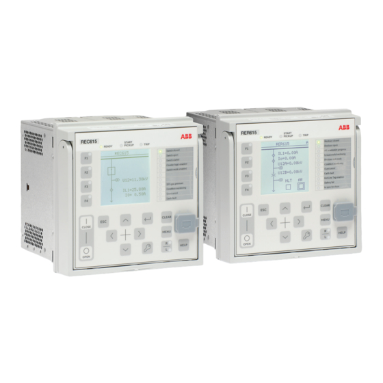
Section 3 1MRS758754 B REC615 and RER615 overview Section 3 REC615 and RER615 overview Overview REC615 and RER615 relays are designed for remote control and monitoring, protection, fault indication, power quality analysis and automation in medium- voltage secondary distribution systems. The design of the relays has been guided by the IEC 61850 standard for communication and interoperability of substation automation devices. -
Page 28: Display
Section 3 1MRS758754 B REC615 and RER615 overview RE_615 START REA DY PIC K UP TRIP Overcur rent Di r. ea rth- f ault Combined P rot ect ion In sync f o close Frequen cy p rot ect ion B rea ker f ailu re Di s turb. - Page 29 Section 3 1MRS758754 B REC615 and RER615 overview Table 5: Large display Rows in the view Characters per row Character size Small, mono-spaced (6 × 12 pixels) Large, variable width (13 × 14 pixels) 8 or more 1) Depending on the selected language The display view is divided into four basic areas.
-
Page 30: Leds
Section 3 1MRS758754 B REC615 and RER615 overview • V: Viewer • O: Operator • E: Engineer • A: Administrator • The content area shows the menu content. • If the menu contains more rows than the display can show at a time, a scroll bar is displayed on the right. - Page 31 Section 3 1MRS758754 B REC615 and RER615 overview 3 4 5 6 7 8 9 10 11 12 13 14 15 GUID-3D1C7915-7FE0-4220-A532-6D8443129246 V1 EN Figure 4: LHMI keypad Function keys Close Open Escape Left Down Right Enter 10 Key 11 Clear 12 Menu 13 Remote/Local 14 Communication port...
- Page 32 Section 3 1MRS758754 B REC615 and RER615 overview Object control If the control position of the protection relay is set to local with the R/L button, the relay can be controlled using the object control buttons. Table 6: Object control push buttons Name Description Closing the object.
-
Page 33: Local Hmi Functionality
Section 3 1MRS758754 B REC615 and RER615 overview Commands Table 8: Command push buttons Name Description • Moving directly to main menu, if currently in any other menu. Menu • Moving between main menu, measurements and single-line diagram views. Changing the control position (remote or local) of the device. •... - Page 34 Section 3 1MRS758754 B REC615 and RER615 overview Table 10: Ready LED LED state Description Auxiliary supply voltage is disconnected. Normal operation. Flashing Internal fault has occurred or the protection relay is in test mode. Internal faults are accompanied by an indication message. Table 11: Start LED LED state...
-
Page 35: Parameter Management
Section 3 1MRS758754 B REC615 and RER615 overview 3.2.4.2 Parameter management The LHMI is used to access the relay parameters. Three types of parameters can be read and written. • Numerical values • String values • Enumerated values Numerical values are presented either in integer or in decimal format with minimum and maximum values. -
Page 36: Web Hmi
Section 3 1MRS758754 B REC615 and RER615 overview A070816 V2 EN Figure 5: RJ-45 communication port and indication LEDs 1 Uplink LED 2 Communication LED When a computer is connected to the protection relay, the relay's DHCP server for the front interface assigns an IP address to the computer. -
Page 37: Command Buttons
Section 3 1MRS758754 B REC615 and RER615 overview The menu tree structure on the WHMI is almost identical to the one on the LHMI. GUID-EC45286A-E8F6-44EA-B63A-9874E23BC24E V2 EN Figure 6: Example view of the WHMI The WHMI can be accessed locally and remotely. •... -
Page 38: Authorization
Section 3 1MRS758754 B REC615 and RER615 overview Name Description Rejecting changes Showing context sensitive help messages Error icon Clearing events Triggering the disturbance recorder manually Saving values to TXT or CSV file format Freezing the values so that updates are not displayed Receiving continuous updates to the monitoring view Deleting the disturbance record Deleting all disturbance records... -
Page 39: Audit Trail
Section 3 1MRS758754 B REC615 and RER615 overview Menu/Configuration/Authorization/Passwords. WHMI always requires authentication. Table 15: Predefined user categories Username User rights VIEWER Read only access OPERATOR • Selecting remote or local state with (only locally) • Changing setting groups • Controlling •... - Page 40 Section 3 1MRS758754 B REC615 and RER615 overview 1686. The logging is based on predefined user names or user categories. The user audit trail events are accessible with IEC 61850-8-1, PCM600, LHMI and WHMI. Table 16: Audit trail events Audit trail event Description Configuration change Configuration files changed...
-
Page 41: Communication
Section 3 1MRS758754 B REC615 and RER615 overview Table 17: Comparison of authority logging levels Audit trail event Authority logging level Configurati Setting Setting Settings None on change group group, edit control Configuration change ● ● ● ● ● Firmware change ●... -
Page 42: Self-Healing Ethernet Ring
Section 3 1MRS758754 B REC615 and RER615 overview values using GOOSE messaging. The protection relay meets the GOOSE performance requirements for tripping applications in distribution substations, as defined by the IEC 61850 standard. The protection relay can support five simultaneous clients. If PCM600 reserves one client connection, only four client connections are left, for example, for IEC 61850 and Modbus. -
Page 43: Ethernet Redundancy
Section 3 1MRS758754 B REC615 and RER615 overview 3.5.2 Ethernet redundancy IEC 61850 specifies a network redundancy scheme that improves the system availability for substation communication. It is based on two complementary protocols defined in the IEC 62439-3:2012 standard: parallel redundancy protocol PRP and high-availability seamless redundancy HSR protocol. - Page 44 Section 3 1MRS758754 B REC615 and RER615 overview COM600 SCADA Ethernet switch Ethernet switch IEC 61850 PRP GUID-334D26B1-C3BD-47B6-BD9D-2301190A5E9D V3 EN Figure 8: PRP solution In case a laptop or a PC workstation is connected as a non-PRP node to one of the PRP networks, LAN A or LAN B, it is recommended to use a redundancy box device or an Ethernet switch with similar functionality between the PRP network and SAN to remove additional PRP information from the Ethernet frames.
-
Page 45: Process Bus
Section 3 1MRS758754 B REC615 and RER615 overview GUID-207430A7-3AEC-42B2-BC4D-3083B3225990 V3 EN Figure 9: HSR solution 3.5.3 Process bus Process bus IEC 61850-9-2 defines the transmission of Sampled Measured Values within the substation automation system. International Users Group created a guideline IEC 61850-9-2 LE that defines an application profile of IEC 61850-9-2 to facilitate implementation and enable interoperability. - Page 46 Section 3 1MRS758754 B REC615 and RER615 overview Common Ethernet Station bus (IEC 61850-8-1), process bus (IEC 61850-9-2 LE) and IEEE 1588 v2 time synchronization GUID-2371EFA7-4369-4F1A-A23F-CF0CE2D474D3 V5 EN Figure 10: Process bus application of voltage sharing and synchrocheck REC615 and RER615 support IEC 61850 process bus with sampled values of analog currents and voltages.
-
Page 47: Secure Communication
Section 3 1MRS758754 B REC615 and RER615 overview Primary Secondary IEEE 1588 v2 IEEE 1588 v2 master clock master clock (optional) Managed HSR Managed HSR Ethernet Ethernet switch switch IEC 61850 Backup 1588 master clock GUID-7C56BC1F-F1B2-4E74-AB8E-05001A88D53D V6 EN Figure 11: Example network topology with process bus, redundancy and IEEE 1588 v2 time synchronization The process bus option is available for REC615 and RER615 protection relays... -
Page 48: Connectivity Packages
Protection and Control IED Manager PCM600 Ver.2.9 or later • REC615 Connectivity Package Ver.2.0 or later • RER615 Connectivity Package Ver.2.0 or later Download connectivity packages from the ABB Web site http://www.abb.com/substationautomation or directly with Update Manager in PCM600. REC615 and RER615... -
Page 49: Section 4 Using The Hmi
Section 4 1MRS758754 B Using the HMI Section 4 Using the HMI Using the local HMI To use the LHMI, logging in and authorization are required. Password authorization is disabled by default and can be enabled via the LHMI. To enable password authorization, select Main menu/ Configuration/Authorization/Passwords. -
Page 50: Logging Out
Section 4 1MRS758754 B Using the HMI A070890 V2 EN Figure 13: Entering password Press to confirm the login. • To cancel the procedure, press A070889 V2 EN Figure 14: Error message indicating wrong password The current user level is shown on the display's upper right corner in the icon area. -
Page 51: Turning The Display Backlight On
Section 4 1MRS758754 B Using the HMI Press To confirm logout, select Yes and press A070837 V3 EN Figure 15: Logging out • To cancel logout, press 4.1.3 Turning the display backlight on The display backlight is normally off. It turns on during the display test at power up. •... -
Page 52: Identifying The Device
Section 4 1MRS758754 B Using the HMI • When the L LED is lit, local control is enabled and remote control disabled. • When the R LED is lit, remote control is enabled and local control disabled. • When neither of the LEDs is lit, both control positions are disabled. •... -
Page 53: Identifying Relay's Iec 61850 Version
Section 4 1MRS758754 B Using the HMI GUID-086DDC6A-D263-4028-8C14-D4C2FF965F92 V2 EN Figure 17: Protection relay information 4.1.5.1 Identifying relay's IEC 61850 version The relay's IEC 61850 version information identifies if the relay is configured as Edition 1 or Edition 2 device. Select Main menu/Information/System identifiers. -
Page 54: Changing The Local Hmi Language
Section 4 1MRS758754 B Using the HMI The selected contrast value is stored in the non-volatile memory if you are logged in and authorized to control the protection relay. After an auxiliary power failure, the contrast is restored. 4.1.7 Changing the local HMI language Select Main menu/Language and press Change the language using Press... -
Page 55: Changing Setting Visibility
Section 4 1MRS758754 B Using the HMI 4.1.9 Changing setting visibility The basic settings contain the most used parameters. The advanced settings contain all parameters. Select Main Menu/Configuration/HMI/Setting visibility and press Change the setting visibility with to select which parameters are shown. -
Page 56: Changing Visibility Of Function Key Texts
Section 4 1MRS758754 B Using the HMI 4.1.10 Changing visibility of function key texts The LHMI keypad on the left side of the protection relay contains four function keys with red LEDs. They can be freely configured both for operation and acknowledgement purposes to get acknowledgements of the executed actions associated with the buttons. -
Page 57: Menu Structure
Section 4 1MRS758754 B Using the HMI • To navigate between main menu, measurements and single-line diagram, press • To move up or down in a menu, press • To move downwards in the menu tree, press • To move upwards in the menu tree, press •... -
Page 58: Changing The Default View
Section 4 1MRS758754 B Using the HMI • To scroll the view upwards, press • To scroll the view downwards, press • To jump from the last row to the first row, press again. • Press to jump from the first row to the last row. •... -
Page 59: Changing Single-Line Diagram Symbol Formats
Section 4 1MRS758754 B Using the HMI GUID-0F9AA31A-A95D-4839-A2AB-DE670272EFA5 V1 EN Figure 25: Single-line diagram with one switch and ANSI symbols Select the single-line diagram for the default view in Main menu/ Configuration/HMI/Default view. When single-line diagram is selected as the default view, the first single-line diagram page is shown when the default view is entered. -
Page 60: Browsing Setting Values
Section 4 1MRS758754 B Using the HMI 4.1.13 Browsing setting values Select Main menu/Settings/Settings and press Select the setting group to be viewed with A070858 V3 EN Figure 27: Selecting a setting group Press to confirm selection. To browse the settings, scroll the list with and to select a submenu press . -
Page 61: Editing Numerical Values
Section 4 1MRS758754 B Using the HMI Changing the function block on or off affects to the visibility of its parameters in the menu. Setting function block off hides the function parameters. When changing function block on or off the parameters' visibility changes immediately. -
Page 62: Editing String Values
Section 4 1MRS758754 B Using the HMI For parameters with defined steps, digits smaller than the step value cannot be edited. Press to move the cursor to another digit. To select the minimum or maximum value, select the arrow symbol in front of the value. -
Page 63: Editing Enumerated Values
Section 4 1MRS758754 B Using the HMI When editing string values, the cursor moves to the first character. Press to change the value of an active character. One press changes the value by one step. Press to move the cursor to another character. •... -
Page 64: Clearing And Acknowledging
Section 4 1MRS758754 B Using the HMI • To exit without saving changes, select No and press • If the parameter has an edit-copy, the original parameter value is restored. • If the parameter does not have an edit-copy, the edited parameter value remains visible until the protection relay is rebooted. -
Page 65: Using The Local Hmi Help
Section 4 1MRS758754 B Using the HMI Use the button as a shortcut for clearing. The first three-second press clears the indications. The second three-second press clears the programmable LEDs. 4.1.17 Using the local HMI help Press to open the help view. Scroll the text with if the help text exceeds the display area. -
Page 66: Logging Out
Section 4 1MRS758754 B Using the HMI GUID-8F9ED19B-76BF-4126-8729-658286BDBE16 V1 EN Figure 34: Entering username and password to use the WHMI Click OK. The language file starts loading and the progress bar is displayed. 4.2.2 Logging out The user is logged out after session timeout. The timeout can be set in Main menu/ Configuration/HMI/Web HMI timeout. -
Page 67: Navigating In Menus
Section 4 1MRS758754 B Using the HMI GUID-8D30A0C7-2910-4204-93C4-DE6721AB9105 V2 EN Figure 35: Device information 4.2.4 Navigating in menus The menu tree structure on the WHMI is almost identical to the one on the LHMI. • Use the menu bar to access different views. •... -
Page 68: Menu Structure
Section 4 1MRS758754 B Using the HMI GUID-510C49B9-F65C-4269-ACB4-C7F0A569F884 V2 EN Figure 36: Navigating in Web HMI menus 4.2.4.1 Menu structure The Main menu contains main groups which are divided further into more detailed submenus. • Control • Events • Measurements •... -
Page 69: Selecting Single-Line Diagram
Section 4 1MRS758754 B Using the HMI 4.2.5 Selecting single-line diagram The single-line diagram is active only when the protection relay is equipped with the large display variant. • Select Control/SLD in the left navigation bar or click Single Line Diagram in the menu bar to view the single-line diagram. -
Page 70: Showing Parameters
Section 4 1MRS758754 B Using the HMI GUID-F433CC42-95D1-4F93-A426-E3ED1F65D23C V3 EN Figure 38: Viewing the single-line diagram with ANSI symbols 4.2.6 Showing parameters Some function blocks have a function-specific On/Off setting. When the function setting is “Off”, all settings are hidden and when the function setting is “On”, all settings are visible based on the other visibility and hiding rules. - Page 71 Section 4 1MRS758754 B Using the HMI The values “Basic” or "Advanced" of the Setting visibility parameter in Main Menu/Configuration/HMI have no effect on the Parameter list page. This page has its own Basic settings option which can be used to hide or show the advanced settings on the Parameter list page. Click Parameter list in the left navigation bar.
-
Page 72: Editing Values
Section 4 1MRS758754 B Using the HMI GUID-54DDC410-4676-4610-BC9E-D7F54F9F76CF V2 EN Figure 40: Enabled settings Select text (.txt) or comma separated values (.csv) file format and click Save to save the settings. Click Print to print all the selected parameters. 4.2.7 Editing values Select a menu in the left navigation bar. - Page 73 Section 4 1MRS758754 B Using the HMI GUID-F4595871-6D65-4A6C-B90C-E60A2F097DCE V2 EN Figure 41: Enable writing to edit a value The selected setting group is shown in the Setting Group drop-down list. The active setting group is indicated with an asterisk *. Edit the value.
-
Page 74: Committing Settings
Section 4 1MRS758754 B Using the HMI GUID-E71F2F31-FF34-40EE-9DD0-19F35EA8E49E V1 EN Figure 43: Warning indicating that the entered value is incorrect • If writing values fails, a warning dialog box is displayed. GUID-D4623C27-645E-4FAA-B288-887FFF99D7B6 V1 EN Figure 44: Warning indicating that the values were not written to the protection relay If writing is enabled accidentally, click Disable Write. - Page 75 Section 4 1MRS758754 B Using the HMI such as string values, are restored to the original value only after a reboot even though the edited value is not stored in the flash memory. Click Write to IED after editing parameter values to put the values into protection relay's database for use.
-
Page 76: Clearing And Acknowledging
Section 4 1MRS758754 B Using the HMI Committing values takes a few seconds. If the values are not committed, they are not taken into use and they are lost after a reboot. 4.2.9 Clearing and acknowledging All messages and indications, including LEDs and latched outputs as well as registers and recordings, can be reset, acknowledged or cleared using the Clear menu. -
Page 77: Selecting Programmable Leds View
Section 4 1MRS758754 B Using the HMI GUID-2194B0F4-FC2C-4D2A-A689-83BAFC095DA3 V2 EN Figure 48: Clearing indications and LEDs 4.2.10 Selecting programmable LEDs view The programmable LEDs view shows the status of the programmable LEDs. These are the same LEDs that are located on the upper right side of the LHMI panel. •... -
Page 78: Selecting Event View
Section 4 1MRS758754 B Using the HMI GUID-A0D61759-8411-482D-A44C-504AB245C110 V2 EN Figure 49: Monitoring programmable LEDs 4.2.11 Selecting event view The event view contains a list of events produced by the application configuration. When the event page is opened, it displays up to 100 latest events at one time. The event list is updated automatically. - Page 79 Section 4 1MRS758754 B Using the HMI GUID-0B5B7F53-8870-4E64-AE33-C4121C502EB1 V2 EN Figure 50: Monitoring events Click Freeze to stop updating the event list. Select a page from the drop-down list to view older events or select View all to show all events on the same page. GUID-70460195-B427-4E08-9F7D-2E576BC7EF1A V2 EN Figure 51: Events view...
-
Page 80: Selecting Disturbance Records View
Section 4 1MRS758754 B Using the HMI The CSV file can be opened with a spreadsheet program such as OpenOffice.org Calc or Microsoft Excel. Click Clear events to clear all events from the protection relay. Click Print to print all the selected events. 4.2.12 Selecting disturbance records view Disturbance records are listed in the disturbance records view. -
Page 81: Triggering Disturbance Recorder Manually
Section 4 1MRS758754 B Using the HMI 4.2.12.2 Triggering disturbance recorder manually Click Disturbance records on the menu bar. Click Manual trigger. GUID-6745166D-6B21-421A-815C-45DF43805233 V2 EN Figure 54: Manual triggering 4.2.12.3 Deleting disturbance records Click Disturbance records on the menu bar. Delete records. -
Page 82: Selecting Phasor Diagrams
Section 4 1MRS758754 B Using the HMI GUID-1AB98D0B-F212-424F-811D-82E1AEA273F7 V2 EN Figure 55: Deleting disturbance records Click OK to confirm or Cancel to cancel the deletion. 4.2.13 Selecting phasor diagrams Install or enable the SVG plugin to view the phasor diagrams, if needed. - Page 83 Section 4 1MRS758754 B Using the HMI GUID-B713AEDC-1D07-4021-A169-9BC26F4376EF V2 EN Figure 56: Monitoring phasors Toggle the diagram visibility by selecting the diagram from the drop-down menu. GUID-D0611800-80E3-48B6-9B76-0D391844A88F V2 EN Figure 57: Toggling the diagram visibility Visible diagrams are indicated with an asterisk *. Change the size of the diagram by changing the zoom value.
- Page 84 Section 4 1MRS758754 B Using the HMI GUID-A28E42D1-E2FD-407A-9E84-D061D0559312 V2 EN Figure 58: Zooming the diagram Click Freeze to stop updating the phasor diagram. No updates are displayed in the diagram. GUID-E92D63AB-11A3-40A0-8783-4EF78BCD7C89 V2 EN Figure 59: The arrow extends outside the circle if the current value is too high REC615 and RER615 Operation Manual...
-
Page 85: Selecting Fault Records
Section 4 1MRS758754 B Using the HMI 4.2.14 Selecting fault records Fom the main menu, select Monitoring/Recorded data/Fault record or click Fault records on the menu bar to view a list of all available fault records. Click a record from the Fault records list to open the fault record details view. -
Page 86: Importing Settings
Section 4 1MRS758754 B Using the HMI GUID-7A4BF554-2CAB-4F53-BF76-4FDE3F78CDC3 V2 EN Figure 60: Selecting Import/Export settings Click Export Settings. The export file includes all parameters except status parameters and parameters writable only in LHMI. Click Save to export the settings to the computer. 4.2.16.2 Importing settings The parameter export and import function can be utilized, for example, when the relay... - Page 87 Section 4 1MRS758754 B Using the HMI Ensure that the correct settings are imported to the correct protection relay. Wrong settings may cause the protection relay to malfunction. Click Import/Export on the menu bar. Click Browse and choose the file to be imported. Click Import Settings.
- Page 88 Section 4 1MRS758754 B Using the HMI GUID-E24675EE-500F-4CE6-A42E-D811968E3BA3 V2 EN Figure 62: Writing parameter settings GUID-E1240949-9954-4A15-A7B1-0F1D6020A5DA V2 EN Figure 63: Parameter settings written to protection relay Only editable parameters are written to the protection relay during the import. If part of the import fails, the faulty parameters are listed separately.
-
Page 89: Exporting Report Summary
Section 4 1MRS758754 B Using the HMI 4.2.17 Exporting report summary The Report summary page allows exporting events, fault records, disturbance records, the load profile record and the parameter list. Events, fault records and the parameter list are saved in TXT format. Saved files contain all events, fault records and settings.Disturbance records and load profile record files are saved in CFG and DAT formats. -
Page 91: Section 5 Protection Relay Operation
Section 5 1MRS758754 B Protection relay operation Section 5 Protection relay operation Normal operation In a normal protection relay use situation, the basic operation includes monitoring and checking procedures. • Monitoring measured values • Checking object states • Checking function setting parameters •... -
Page 92: Disturbance Recording Triggering
Section 5 1MRS758754 B Protection relay operation Document the disturbance before clearing the information from the protection relay. Only authorized and skilled personnel should analyze possible errors and decide on further actions. Otherwise, stored disturbance data can be lost. 5.2.1 Disturbance recording triggering Disturbance recordings are normally triggered by protection relay applications when they detect fault events. -
Page 93: Relay Parametrization
Section 5 1MRS758754 B Protection relay operation Only authorized and skilled personnel should analyze the errors and decide on further actions. The protection relay records system registrations, relay status data and events. Document all the recorded data from the protection relay before resetting the tripping and relay lockout functions. -
Page 95: Section 6 Operating Procedures
Section 6 1MRS758754 B Operating procedures Section 6 Operating procedures Monitoring 6.1.1 Indications The operation of the protection relay can be monitored via three different indications on the LHMI. • Three indicator LEDs with fixed functionality: Ready, Start and Trip •... -
Page 96: Monitoring An Internal Relay Fault
Section 6 1MRS758754 B Operating procedures 6.1.1.2 Monitoring an internal relay fault The flashing green LED indicates an internal relay fault. Internal relay fault messages are shown in a dialog box. Only one dialog box can be shown at a time, therefore the relay has internal priority for indication messages and tripping data. -
Page 97: Measured Values
Section 6 1MRS758754 B Operating procedures Invalid or questionable measurement values are presented in parentheses. 6.1.2.1 Measured values Measured values can be accessed through the LHMI, WHMI or PCM600. Table 19: Examples of the measured values Indicator Description IL1-A Current measured on phase L1 IL2-A Current measured on phase L2 IL3-A... -
Page 98: Creating Disturbance Recordings
Section 6 1MRS758754 B Operating procedures • Disturbance records • Fault records • Events • Load profile record 6.1.3.1 Creating disturbance recordings Normally disturbance recordings are triggered by the protection relay applications but the recording can also be triggered manually. Select Main menu/Disturbance records. -
Page 99: Controlling And Reading Of Disturbance Recorder Data
Section 6 1MRS758754 B Operating procedures • Number of recordings currently in the protection relay's memory. • Remaining amount of recordings that fit into the available recording memory. • Recording memory used in percentage. • If the periodic triggering function is used, the time to trigger which indicates the remaining time to the next periodic triggering of the disturbance recorder. -
Page 100: Monitoring Events
Section 6 1MRS758754 B Operating procedures GUID-C0599963-43D7-49AA-9912-D55CAEDFD3F7 V1 EN Figure 69: Monitoring fault records 6.1.3.5 Monitoring events Event view contains a list of events produced by the application configuration. Each event takes one view area. The header area shows the currently viewed event index and the total amount of the events. -
Page 101: Monitoring And Saving Load Profile Record
Section 6 1MRS758754 B Operating procedures 6.1.3.6 Monitoring and saving load profile record • Monitor the recording memory usage of the load profile via Main menu/ Monitoring/Load profile record. • Save and analyze the load profile record with PCM600. 6.1.4 Remote monitoring The protection relay supports comprehensive remote monitoring. -
Page 102: Controlling Sld Buttons
Section 6 1MRS758754 B Operating procedures GUID-1F3D36EE-0930-4E3E-A40B-89389E6EA903 V1 EN Figure 71: Single-line diagram with one switch and IEC symbols GUID-0F9AA31A-A95D-4839-A2AB-DE670272EFA5 V1 EN Figure 72: Single-line diagram with one switch and ANSI symbols The selected object has a square around it. Press to open or to close the selected object. -
Page 103: Controlling Single-Line Diagram Tap Changer
Section 6 1MRS758754 B Operating procedures GUID-BF9C2038-2E24-4530-B9DF-8448E535F9EC V1 EN Figure 73: Single-line diagram with several buttons. The CNT_LOGIC button is in “On” state and the SW_MODE button is selected and it is currently in “Off” state The selected button has a square around it. Press to control the selected button. -
Page 104: Controlling Via The Control Menu
Section 6 1MRS758754 B Operating procedures 6.2.2 Controlling via the control menu The primary equipment can be controlled via the LHMI with the Open and Close buttons when the protection relay is set to the local-control mode and accessing the control operations is authorized. -
Page 105: Controlling With The Closing Delay
Section 6 1MRS758754 B Operating procedures A071172 V3 EN Figure 77: Cancelling operation The time between selecting the object and giving a control command is restricted by an adjustable time-out. When an object is selected, the control command has to be given within this time. With default configurations it is possible to control a breaker open even when the breaker is in an intermediate state. -
Page 106: Resetting Protection Relay
Section 6 1MRS758754 B Operating procedures GUID-BB0A736A-A5EA-423E-824E-F9580C3F75D6 V1 EN Figure 78: Delay view When the delay is activated, it is recommended not to change any closing delay parameters in the WHMI during the delayed time as it affects the delayed circuit breaker closing. If the delayed circuit breaker closing fails, the LHMI status shows Select timeout or Status only. - Page 107 Section 6 1MRS758754 B Operating procedures • Load profile record • Acc. energy of circuit breaker condition monitoring, three-phase power and energy measurement and single-phase power and energy measurement • Rem. life of circuit breaker condition monitoring • Travel times of circuit breaker condition monitoring •...
-
Page 108: Changing Protection Relay Functionality
Section 6 1MRS758754 B Operating procedures Changing protection relay functionality 6.4.1 Defining the setting group 6.4.1.1 Activating a setting group Protection relay settings are planned in advance for different operation conditions by calculating setting values to different setting groups. The active setting group can be changed by the protection relay application or manually from the menu. -
Page 109: Copying A Setting Group
Section 6 1MRS758754 B Operating procedures Remember to document the changes you make. 6.4.1.2 Copying a setting group Setting group 1 can be copied to another group or to all available groups. Select Main menu/Settings/Setting group/Copy group 1 and press Change the options with and press to confirm the selection. - Page 110 Section 6 1MRS758754 B Operating procedures A071166 V3 EN Figure 83: Selecting a setting group To browse the settings, scroll the list with and to select a setting press To browse different function blocks, scroll the list with and to select a function block press .
-
Page 111: Activating Programmable Leds
Section 6 1MRS758754 B Operating procedures A071168 V4 EN Figure 85: Selecting the setting group value Only values within the selected setting group can be changed. Press to change the value and to confirm the selection. A070922 V4 EN Figure 86: Editing the setting group value The active setting group is indicated with an asterisk * . -
Page 112: Setting Autoscroll Delay
Section 6 1MRS758754 B Operating procedures See the technical manual for details on LED configuration. 6.4.3 Setting autoscroll delay Autoscroll delay parameter sets the delay of scrolling down measurements view if it is set as default view and the user is logged out. Autoscroll is active if the delay value is not zero. -
Page 113: Section 7 Troubleshooting
Inspect the protection relay visually. • Inspect the protection relay visually to find any physical error causes. • If you can find some obvious physical damage, contact ABB for repair or replacement actions. Check whether the error is external or internal. •... -
Page 114: Checking Time Synchronization
Section 7 1MRS758754 B Troubleshooting Table 20: Front communication LEDs Communication ok Uplink Steady green light Communication Flashing yellow light 7.1.3.2 Checking time synchronization • Check the time synchronization via LHMI in Main menu/Monitoring/IED status/Time synchronization. 7.1.4 Running the display test A short display test is always run, when auxiliary voltage is connected to the protection relay. - Page 115 1MRS758754 B Troubleshooting The internal fault code indicates the type of internal relay fault. When a fault appears, the code must be recorded so that it can be reported to ABB customer service. A071144 V3 EN Figure 88: Fault indication...
-
Page 116: Warnings
Section 7 1MRS758754 B Troubleshooting Fault indication Fault code Additional information Internal Fault Card in slot X100 is wrong type or does not Conf. error,X100 belong to the original composition. Internal Fault Card in slot X110 is wrong type, is missing Conf. - Page 117 Section 7 1MRS758754 B Troubleshooting If a warning appears, record the name and code so that it can be provided to ABB customer service. A071222 V2 EN Figure 89: Warning Table 22: Warning indications and codes Warning indication Warning code...
-
Page 118: Correction Procedures
Section 7 1MRS758754 B Troubleshooting Warning indication Warning code Additional information Warning Analog channel configuration error. AFL error Warning Error in the SMV configuration. SMV config error Warning Redundant Ethernet (HSR/PRP) Comm. channel down communication interrupted. Warning A new composition has not been Unack card comp. -
Page 119: Setting Passwords
, change the password with and press again. Repeat steps 2 and 3 to set the rest of the passwords. If the administrator password is lost, contact ABB's technical customer support to retrieve the administrator level access. 7.3.4 Identifying relay application problems •... -
Page 120: Sample Data Interruptions
In case of permanent faults, the measurement chain should be checked to remove the origin of the faulty measurement data. In case of persistent faults originating from protection relay's internal faults, contact ABB for repair or replacement actions. REC615 and RER615 Operation Manual... -
Page 121: Section 8 Commissioning
Section 8 1MRS758754 B Commissioning Section 8 Commissioning Commissioning checklist Familiarize yourself with the protection relay and its functionality before you start the commissioning work. • Ensure that you have all the needed station drawings such as single line and wiring diagrams. -
Page 122: Checking Ct Circuits
Section 8 1MRS758754 B Commissioning 8.2.2 Checking CT circuits Check that the wiring is in strict accordance with the supplied connection diagram. The CTs must be connected in accordance with the terminal diagram provided with the protection relay, both with regards to phases and polarity. The following tests are recommended for every primary CT or CT core connected to the protection relay. -
Page 123: Checking Binary Input And Output Circuits
Section 8 1MRS758754 B Commissioning Correct possible errors before continuing to test the circuitry. Test the circuitry. • Polarity check • VT circuit voltage measurement (primary injection test) • Earthing check • Phase relationship • Insulation resistance check The polarity check verifies the integrity of circuits and the phase relationships. The polarity must be measured as close to the protection relay as possible to ensure that most of the wiring is also checked. -
Page 124: Authorizations
Section 8 1MRS758754 B Commissioning Authorizations 8.3.1 User authorization The user categories have been predefined for the LHMI and WHMI, each with different rights and default passwords. Passwords are settable for all predefined user categories. The LHMI password must be at least four and WHMI password at least nine characters. The maximum number of characters is 8 for the LHMI password and 20 for the WHMI password. -
Page 125: Setting Protection Relay And Communication
Section 8 1MRS758754 B Commissioning Setting protection relay and communication 8.4.1 Setting the communication between protection relays and PCM600 The communication between the protection relay and PCM600 is independent of the used communication protocol within the substation or to the NCC. It can be seen as a second channel for communication. -
Page 126: Communication Settings
Section 8 1MRS758754 B Commissioning LAN or WAN network In TCP/IP networking, a LAN is often but not always implemented as a single IP subnet. A router connects LANs to a WAN. In IP networking, the router maintains both a LAN address and a WAN address. Design considerations for computer networks cover a wide range of topics including layout, capacity planning, and security. -
Page 127: Serial Communication Ports And Drivers
Section 8 1MRS758754 B Commissioning For more information, see the communication protocol manuals and the technical manual. 8.4.2.1 Serial communication ports and drivers Depending on the hardware configuration, the protection relay can be equipped with one or several UART-based serial communication ports. The communication ports can be either galvanic (RS-485, RS-232) or fiber optic. -
Page 128: Serial Link Diagnostics And Monitoring
Section 8 1MRS758754 B Commissioning In addition to setting the COM parameter, a communication card with many hardware options may also require changing the jumpers on the communication card. Connection of a serial communication protocol to a specific serial port The serial communication protocol (instance) settings include a setting parameter called Serial port n (n = protocol instance number). - Page 129 Section 8 1MRS758754 B Commissioning Parameter Range Type Description Transmission 0…2147483646 Detailed Number of transmission timeout errors. timeout Parity errors 0…2147483646 Detailed Number of character parity errors detected. Overrun errors 0…2147483646 Detailed Number of character overrun errors detected. Framing errors 0…2147483646 Detailed Number of character overrun errors...
-
Page 130: Defining Ethernet Port Settings
Section 8 1MRS758754 B Commissioning Counter Function Transmission timeout. In RS-232 handshake mode. If the CTS signal goes inactive during transmission then the transmission is halted. Transmission will be resumed when CTS goes active again. The whole frame transmission must anyhow be ready within a specified time. -
Page 131: Setting Communication Protocol Parameters
Section 8 1MRS758754 B Commissioning 8.4.2.5 Setting communication protocol parameters Select Main menu/Configuration/Communication/<protocol>. Change the protocol specific settings. Possible settings to be changed are, for example, the selected communication port, address and link mode. 8.4.2.6 Connecting jumper connectors See the technical manual for details on jumper connectors. 8.4.3 Setting the local HMI 8.4.3.1... -
Page 132: Adjusting The Display Contrast
Section 8 1MRS758754 B Commissioning 8.4.3.2 Adjusting the display contrast Adjust the display contrast anywhere in the menu structure to obtain optimal readability. • To increase the contrast, press simultaneously • To decrease the contrast, press simultaneously The selected contrast value is stored in the non-volatile memory if you are logged in and authorized to control the protection relay. - Page 133 Section 8 1MRS758754 B Commissioning Select Main menu/Configuration/Time/Synchronization/Synch source and press Select the time synchronization source with Press to confirm the selection. Setting daylight saving time The protection relay can be set to determine the correct date for the DST shift every year.
-
Page 134: Setting Protection Relay Parameters
Section 8 1MRS758754 B Commissioning Repeat the setting yearly, as the time for the DST shift is not on the same date every year. To disable the DST, set the DST in use parameter to "False". 8.4.4 Setting protection relay parameters 8.4.4.1 Defining setting groups Selecting a setting group for editing... - Page 135 Section 8 1MRS758754 B Commissioning A071166 V3 EN Figure 92: Selecting a setting group To browse the settings, scroll the list with and to select a setting press To browse different function blocks, scroll the list with and to select a function block press .
- Page 136 Section 8 1MRS758754 B Commissioning A071168 V4 EN Figure 94: Selecting the setting group value Only values within the selected setting group can be changed. Press to change the value and to confirm the selection. A070922 V4 EN Figure 95: Editing the setting group value The active setting group is indicated with an asterisk * .
-
Page 137: Relay Parametrization
Section 8 1MRS758754 B Commissioning A071150 V3 EN Figure 96: Active setting group Select the setting group with Press to confirm the selection or to cancel. A071152 V3 EN Figure 97: Selecting the active setting group Commit the settings. Remember to document the changes you make. 8.4.4.2 Relay parametrization Protection relay parameters are set via the LHMI, WHMI or PCM600. -
Page 138: Defining Disturbance Recorder Channel Settings
Section 8 1MRS758754 B Commissioning Document all changes to parameter settings. For more information, see the PCM600 documentation. 8.4.4.3 Defining disturbance recorder channel settings Select Main Menu/Configuration/Disturbance recorder/Channel settings. Press to select the wanted channel and parameter. To change channel settings, press Each analog channel has an equal set of parameters and correspondingly, each binary channel has an equal set of parameters. -
Page 139: Testing The Digital I/O Interface
Section 8 1MRS758754 B Commissioning The Ready LED also flashes if the protection relay detects a diagnostic failure. Check the test mode setting and the protection relay's IRF alarm contact status to find the reason for the failure. The test mode is useful for simulated testing of functions and outputs without providing current inputs. -
Page 140: Testing Functions
Section 8 1MRS758754 B Commissioning 8.5.3 Testing functions Activate or deactivate an output signal for protection or other function to test the function. Select Main Menu/Tests/Function tests/Current protection/<function block name> and press Select the output signal to be activated or deactivated with and press To deactivate all output signals for the function, select Reset with and press... -
Page 141: Selecting The Ied Blocked Or Ied Test And Blocked Mode
If the IED blocked or IED test and blocked mode is not cancelled, it remains on and the Start and/or Ready LEDs remain flashing. ABB Product Data Registration The ABB Product Data Registration feature traces composition changes in the protection relay's SW or HW. Traceability allows better support and maintenance possibilities. - Page 142 Section 8 1MRS758754 B Commissioning After a composition change, an LCT indication is seen on the LHMI at the protection relay startup. The PCM600 reads the changed data from the protection relay. Therefore a connection to the protection relay must be established first. Composition data can be read with PCM600 by enabling LCT during PCM600 installation and activating collection in PCM600 from 'Lifecycle Handling' menu.
-
Page 143: Section 9 Glossary
Section 9 1MRS758754 B Glossary Section 9 Glossary 100BASE-FX A physical medium defined in the IEEE 802.3 Ethernet standard for local area networks (LANs) that uses fiber optic cabling 100BASE-TX A physical medium defined in the IEEE 802.3 Ethernet standard for local area networks (LANs) that uses twisted-pair cabling category 5 or higher with RJ-45 connectors Alternating current... - Page 144 Section 9 1MRS758754 B Glossary FIFO First in, first out Firmware System software or hardware that has been written and stored in a device's memory that controls the device FPGA Field-programmable gate array File transfer protocol FTPS FTP Secure GOOSE Generic Object-Oriented Substation Event Human-machine interface High-availability seamless redundancy...
- Page 145 Section 9 1MRS758754 B Glossary Life cycle traceability Light Edition Light-emitting diode LHMI Local human-machine interface Media access control 1. Manufacturing message specification 2. Metering management system Modbus A serial communication protocol developed by the Modicon company in 1979. Originally used for communication in PLCs and RTU devices.
- Page 146 Section 9 1MRS758754 B Glossary phases with a separate line or terminal, only one conductor is represented. Single-line diagram Signal Matrix tool in PCM600 Sampled measured values SNTP Simple Network Time Protocol Connector type for glass fiber cable Shielded twisted-pair Scalable vector graphics Software TCP/IP...
- Page 148 — ABB Distribution Solutions Distribution Automation P.O. Box 699 FI-65101 VAASA, Finland Phone +358 10 22 11 www.abb.com/mediumvoltage www.abb.com/relion © Copyright 2019 ABB. All rights reserved.
Need help?
Do you have a question about the RELION REC615 and is the answer not in the manual?
Questions and answers