Table of Contents
Advertisement
Quick Links
OUTDOOR UNIT
SERVICE MANUAL
Models
MUZ-AP15VG
MUZ-AP20VG
-
-
-
E1
ET1
ER1
,
,
-
-
-
-
E1
ET1
ER1
E2
,
,
,
CONTENTS
1. TECHNICAL CHANGES ······························2
USING REFRIGERANT R32 ·························3
3. PART NAMES AND FUNCTIONS ··················5
4. SPECIFICATION ········································6
5. NOISE CRITERIA CURVES ··························8
6. OUTLINES AND DIMENSIONS ·····················9
7. WIRING DIAGRAM ··································· 10
8. REFRIGERANT SYSTEM DIAGRAM ··········· 12
9. PERFORMANCE CURVES ························· 14
10. ACTUATOR CONTROL ····························· 23
11. SERVICE FUNCTIONS ······························ 24
12. TROUBLESHOOTING ······························· 25
13. DISASSEMBLY INSTRUCTIONS ················· 45
PARTS CATALOG (OBB839)
Revision C:
• MUZ-AP20VG-
has been added.
E2
OBH839 REVISED EDITION-B is void.
No. OBH839
HFC
REVISED EDITION-C
utilized
R32
Indoor unit service manual
MSZ-AP•VG Series (OBH838)
Advertisement
Chapters
Table of Contents

Related Manuals for Mitsubishi Electric MUZ-AP15VG


Summary of Contents for Mitsubishi Electric MUZ-AP15VG
-
Page 1: Table Of Contents
OBH839 REVISED EDITION-B is void. OUTDOOR UNIT No. OBH839 REVISED EDITION-C utilized SERVICE MANUAL Models MUZ-AP15VG MUZ-AP20VG Indoor unit service manual MSZ-AP•VG Series (OBH838) CONTENTS 1. TECHNICAL CHANGES ······························2 2. SERVICING PRECAUTIONS FOR UNITS USING REFRIGERANT R32 ·························3 3. -
Page 2: Technical Changes
When pumping down the refrigerant, stop the compressor before disconnecting the refrigerant pipes. The compressor may burst if air etc. get into it. Revision A: • MUZ-AP20VG- have been added. Revision B: • MUZ-AP15VG- have been added. Revision C: • MUZ-AP20VG- has been added. TECHNICAL CHANGES... -
Page 3: Servicing Precautions For Units Using Refrigerant R32
SERVICING PRECAUTIONS FOR UNITS USING REFRIGERANT R32 Servicing precautions for units using refrigerant R32 WARNING This unit uses a flammable refrigerant. If refrigerant leaks and comes in contact with fire or heating part, it will create harmful gas and there is risk of fire. Do not use means to accelerate the defrosting process or to clean, other than those recommended by the manufacturer. T he appliance shall be stored in a room without continuously operating ignition sources (for example: open flames, an operating gas appliance or an operating electric heater.) Do not pierce or burn. Be aware that refrigerants may not contain an odor. Pipe-work shall be protected from physical damage. The installation of pipe-work shall be kept to a minimum. Compliance with national gas regulations shall be observed. Keep any required ventilation openings clear of obstruction. Servicing shall be performed only as recommended by the manufacturer. The appliance shall be stored so as to prevent mechanical damage from occurring. - Page 4 5. Detection of Flammable Refrigerants U nder no circumstances shall potential sources of ignition be used in the searching for or detection of refrigerant leaks. A halide torch (or any other detector using a naked flame) shall not be used. 6. Leak Detection Methods E lectronic leak detectors may be used to detect refrigerant leaks but, in the case of flammable refrigerants, the sensitivity may not be adequate, or may need re-calibration. (Detection equipment shall be calibrated in a refrigerant-free area.) Ensure that the detector is not a potential source of ignition and is suitable for the refrigerant used. Leak detection equipment shall be set at a percentage of the LFL of the refrigerant and shall be calibrated to the refrigerant employed, and the appropriate percentage of gas (25 % maximum) is confirmed. L eak detection fluids are suitable for use with most refrigerants but the use of detergents containing chlorine shall be avoided as the chlorine may react with the refrigerant and corrode the copper pipe-work. If a leak is suspected, all naked flames shall be removed/extinguished. I f a leakage of refrigerant is found which requires brazing, all of the refrigerant shall be recovered from the system, or isolated (by means of shut off valves) in a part of the system remote from the leak. For appliances containing flammable refrigerants, oxygen free nitrogen (OFN) shall then be purged through the system both before and during the brazing process. 7. Removal and Evacuation W hen breaking into the refrigerant circuit to make repairs - or for any other purpose conventional procedures shall be used. However, for flammable refrigerants it is important that best practice is followed since flammability is a consideration. The following procedure shall be adhered to: ▪ remove refrigerant ▪ purge the circuit with inert gas ▪ evacuate ▪ purge again with inert gas ▪ open the circuit by cutting or brazing. T he refrigerant charge shall be recovered into the correct recovery cylinders. For appliances containing flammable refrigerants, the system shall be "flushed" with OFN to render the unit safe. This process may need to be repeated several times. Compressed air or oxygen shall not be used for purging refrigerant systems. F or appliances containing flammable refrigerants, flushing shall be achieved by breaking the vacuum in the system with OFN and continuing to fill until the working pressure is achieved, then venting to atmosphere, and finally pulling down to a vacuum. This process shall be repeated until no refrigerant is within the system. When the final OFN charge is used, the system shall be vented down to atmospheric pressure to enable work to take place. This operation is absolutely vital if brazing operations on the pipe-work are to take place.
-
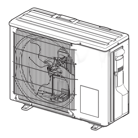
Page 5: Part Names And Functions
PART NAMES AND FUNCTIONS MUZ-AP15VG Air inlet (Back) Piping Drain hose Air outlet Drain outlet MUZ-AP20VG Air inlet (Back and side) Piping Air outlet Drain hose Drain outlet ACCESSORIES MUZ-AP15VG MODELS MUZ-AP20VG Drain socket OBH839C... -
Page 6: Specification
SPECIFICATION Outdoor model MUZ-AP15VG MUZ-AP20VG Power supply Single phase, 230 V, 50 Hz 1.5 (0.5 - 2.2) 2.0 (0.6 - 2.7) Cooling Capacity Rated (Min.-Max.) 2.0 (0.5 - 3.1) 2.5 (0.5 - 3.5) Heating Breaker Capacity Cooling Power input *1 (Set) Heating Cooling Running current *1 (Set) Heating Cooling Power factor *1 (Set) Heating Starting current *1 (Set) Coefficient of performance Cooling 4.17 4.35 (COP) *1 (Set) Heating 4.00 4.17 Model KVB059FTMMC KVB073FYXMC Output Compressor Cooling 1.69 2.19... - Page 7 Specifications and rated conditions of main electric parts Model MUZ-AP15VG MUZ-AP20VG Item (C62) 600 µF/ 620 µF 420 V 800 µF 420 V Smoothing capacitor (C63) 600 µF/ 620 µF 420 V — (DB61) 15 A 600 V Diode module (DB65) 25 A 600 V (F61) 15A 250V 25A 250V...
-
Page 8: Noise Criteria Curves
NOISE CRITERIA CURVES MUZ-AP15VG MUZ-AP20VG FAN SPEED FUNCTION SPL(dB(A)) LINE FAN SPEED FUNCTION SPL(dB(A)) LINE COOLING COOLING Super High Super High HEATING HEATING NC-70 NC-70 NC-60 NC-60 NC-50 NC-50 NC-40 NC-40 NC-30 NC-30 NC-20 NC-20 NC-10 NC-10 1000 2000 4000... -
Page 9: Outlines And Dimensions
OUTLINES AND DIMENSIONS MUZ-AP15VG Unit: mm MUZ-AP20VG OBH839C... -
Page 10: Wiring Diagram
WIRING DIAGRAM MUZ-AP15VG - MUZ-AP15VG - OBH839C... - Page 11 MUZ-AP20VG - MUZ-AP20VG - OBH839C...
-
Page 12: Refrigerant System Diagram
REFRIGERANT SYSTEM DIAGRAM MUZ-AP15VG Unit: mm Refrigerant pipe ø9.52 4-way valve (with heat insulator) Muffler Outdoor heat exchanger Stop valve temperature (with service port) thermistor Outdoor Muffler RT68 Discharge heat Flared connection temperature exchanger thermistor RT62 Ambient Compressor temperature thermistor... - Page 13 MAX. REFRIGERANT PIPING LENGTH and MAX. HEIGHT DIFFERENCE Refrigerant piping: m Piping size O.D: mm Model Max. Length A Max. Height difference B Liquid MUZ-AP15VG 9.52 6.35 MUZ-AP20VG Indoor unit Max. Height difference Max. Length Outdoor unit ADDITIONAL REFRIGERANT CHARGE (R32: g) Refrigerant piping length (one way) Outdoor unit Model precharged 10 m 11 m...
-
Page 14: Performance Curves
PERFORMANCE CURVES MUZ-AP15VG MUZ-AP20VG The standard specifications apply only to the operation of the air conditioner under normal conditions. Since operating condi- tions vary according to the areas where these units are installed, the following information has been provided to clarify the oper- ating characteristics of the air conditioner under the conditions indicated by the performance curve. (1) GUARANTEED VOLTAGE 198 ~ 264 V, 50 Hz (2) AIRFLOW Airflow should be set at MAX. (3) MAIN READINGS (1) Indoor intake air wet-bulb temperature: °C [WB] (2) Indoor outlet air wet-bulb temperature: °C [WB] Cooling (3) Outdoor intake air dry-bulb temperature: °C [DB] (4) Total input: (5) Indoor intake air dry-bulb temperature: °C [DB] (6) Outdoor intake air wet-bulb temperature: °C [WB] Heating (7) Total input: Indoor air wet and dry bulb temperature difference on the left side of the following chart shows the difference between the indoor intake air wet and dry bulb temperature and the indoor outlet air wet and dry bulb temperature for your reference at service. How to measure the indoor air wet and dry bulb temperature difference 1. Attach at least 2 sets of wet and dry bulb thermometers to the indoor air intake as shown in the figure, and at least 2 sets of... - Page 15 13.3 15.5 11.8 13.8 10.4 12.1 10.3 Outdoor intake air Wet-bulb temperature (°C) Total input (Heating : at Rated frequency Outdoor intake air Wet-bulb temperature (°C) Lower limit of guaranteed operating range in heating MUZ-AP15VG: -15°C MUZ-AP20VG: -15°C NOTE: The above broken lines are for the heating operation without any frost and defrost operation. OBH839C...
-
Page 16: Muz-Ap20Vg
9-2. CAPACITY AND INPUT CORRECTION BY OPERATIONAL FREQUENCY OF COMPRESSOR MUZ-AP15VG Correction of Cooling capacity Correction of Cooling input Correction of Heating input Correction of Heating capacity The operational frequency The operational frequency The operational frequency The operational frequency of compressor (Hz) - Page 17 Outdoor unit current MUZ-AP15VG MUZ-AP20VG Ambient temperature (°C) Ambient temperature (°C) Ambient humidity(%) Ambient humidity(%) HEAT operation Condition: Indoor Outdoor Dry bulb temperature (°C) 20.0 20.0 Wet bulb temperature (°C) 14.5 14.5 Operation: Test run operation (Refer to 9-3.) Outdoor unit current MUZ-AP20VG MUZ-AP15VG Ambient temperature (°C) Ambient temperature (°C) OBH839C...
- Page 18 PERFORMANCE DATA COOL operation at Rated frequency MUZ-AP15VG CAPACITY: 1.5 kW SHF: 0.86 INPUT: 370 W OUTDOOR DB (°C) INDOOR INDOOR DB (°C) WB (°C) INPUT INPUT INPUT INPUT 1.76 1.20 0.68 1.69 1.15 0.68 1.62 1.10 0.68 1.56 1.06 0.68 1.84 1.03 0.56 1.76 0.99 0.56 1.71 0.96 0.56...
- Page 19 PERFORMANCE DATA COOL operation at Rated frequency MUZ-AP15VG CAPACITY: 1.5 kW SHF: 0.86 INPUT: 370 W OUTDOOR DB (°C) INDOOR INDOOR DB (°C) WB (°C) INPUT INPUT INPUT 1.47 1.00 0.68 1.35 0.92 0.68 1.25 0.85 0.68 1.55 0.87 0.56 1.44 0.81 0.56 1.34 0.75 0.56 1.47 1.06 0.72 1.35...
- Page 20 PERFORMANCE DATA COOL operation at Rated frequency MUZ-AP20VG CAPACITY: 2.0 kW SHF: 0.8 INPUT: 460 W OUTDOOR DB (°C) INDOOR INDOOR DB (°C) WB (°C) INPUT INPUT INPUT INPUT 2.35 1.46 0.62 2.25 1.40 0.62 2.16 1.34 0.62 2.08 1.29 0.62 2.45 1.23 0.50 2.35 1.18 0.50 2.28 1.14 0.50 2.20 1.10...
- Page 21 PERFORMANCE DATA COOL operation at Rated frequency MUZ-AP20VG CAPACITY: 2.0 kW SHF: 0.8 INPUT: 460 W OUTDOOR DB (°C) INDOOR INDOOR DB (°C) WB (°C) INPUT INPUT INPUT 1.96 1.22 0.62 1.80 1.12 0.62 1.66 1.03 0.62 2.06 1.03 0.50 1.92 0.96 0.50 1.78 0.89 0.50 1.96 1.29 0.66 1.80 1.19 0.66...
- Page 22 PERFORMANCE DATA HEAT operation at Rated frequency MUZ-AP15VG CAPACITY: 2.0kW INPUT: 500 W OUTDOOR WB (°C) INDOOR DB (°C) INPUT INPUT INPUT INPUT INPUT INPUT INPUT INPUT 1.00 1.26 1.52 1.78 2.04 2.30 2.54 2.80 0.94 1.20 1.44 1.70 1.94 2.20 2.44 2.69 0.82 1.08 1.34 1.58...
-
Page 23: Actuator Control
ACTUATOR CONTROL MUZ-AP15VG MUZ-AP20VG 10-1. OUTDOOR FAN MOTOR CONTROL The fan motor turns ON/OFF, interlocking with the compressor. [ON] The fan motor turns ON 5 seconds before the compressor starts up. [OFF] The fan motor turns OFF 15 seconds after the compressor has stopped running. 5 seconds 15 seconds Compressor Outdoor fan motor 10-2. R.V. COIL CONTROL Heating ....ON Cooling . -
Page 24: Service Functions
SERVICE FUNCTIONS MUZ-AP15VG MUZ-AP20VG 11-1. CHANGE IN DEFROST SETTING Changing defrost finish temperature <JS> To change the defrost finish temperature, cut/solder the JS wire of the outdoor inverter P.C. board. (Refer to 12-6-1.) Defrost finish temperature (°C) Jumper wire Soldered (Initial setting) None (Cut) 11-2. PRE-HEAT CONTROL SETTING PRE-HEAT CONTROL When moisture gets into the refrigerant cycle, it may interfere the start-up of the compressor at low outside temperature. The pre-heat control prevents this interference. The pre-heat control turns ON when the discharge temperature thermistor is 20°C or below. When the pre-heat control turns ON, the compressor is energized. (About 50 W) -
Page 25: Troubleshooting
TROUBLESHOOTING MUZ-AP15VG MUZ-AP20VG 12-1. CAUTIONS ON TROUBLESHOOTING 1. Before troubleshooting, check the following 1) Check the power supply voltage. 2) Check the indoor/outdoor connecting wire for miswiring. 2. Take care of the following during servicing 1) Before servicing the air conditioner, be sure to turn OFF the main unit first with the remote controller, and then after confirming the horizontal vane is closed, turn OFF the breaker and/or disconnect the power plug. 2) Be sure to turn OFF the power supply before removing the front panel, the cabinet, the top panel, and the electronic control P.C. board. 3) When removing the electrical parts, be careful of the residual voltage of smoothing capacitor. - Page 26 12-2. FAILURE MODE RECALL FUNCTION Outline of the function This air conditioner can memorize the abnormal condition which has occurred once. Even though LED indication listed on the troubleshooting check table (12-3.) disappears, the memorized failure details can be recalled. 1. Flow chart of failure mode recall function for the indoor/outdoor unit Operational procedure The cause of abnormality cannot be found because the abnormality does not recur. Setting up the failure mode recall function Turn ON the power supply. <Preparation of the remote controller> While pressing Operation select button and TEMP button on the remote controller at the same time, press RESET button.
- Page 27 2. Flow chart of the detailed outdoor unit failure mode recall function Operational procedure The outdoor unit might be abnormal. Check if outdoor unit is abnormal according to the following procedures. Make sure that the remote controller is set to the failure mode recall function. 1. Regardless of normal or abnormal condition, 2 short With the remote controller headed towards the indoor unit, press TEMP button to adjust the set temperature to 25°C. *1 beeps are emitted as the signal is received.
- Page 28 3. Table of outdoor unit failure mode recall function NOTE: Blinking patterns of this mode differ from the ones of TROUBLESHOOTING CHECK TABLE (12-3.). Indoor/outdoor Outdoor unit Abnormal point LED indication unit failure Upper lamp Remedy Condition failure mode (Indoor unit) (Failure mode/protection) (Outdoor P.C. board) mode recall recall function function None (Normal) — — — — — 1-time blink Indoor/outdoor Any signals from the inverter P.C.
- Page 29 NOTE: Blinking patterns of this mode differ from the ones of TROUBLESHOOTING CHECK TABLE (12-3.). Indoor/outdoor Outdoor unit Upper lamp Abnormal point LED indication unit failure Remedy Condition failure mode (Indoor unit) (Failure mode/protection) (Outdoor P.C. board) mode recall recall function function 10-time blink • Refer to 12-5. "Check Discharge temperature Temperature of discharge temperature ○ thermistor has been 50°C or less for of LEV". 2.5 seconds •...
- Page 30 12-3. TROUBLESHOOTING CHECK TABLE Abnormal point/ Symptom Remedy LED indication Condition Condition 1-time blink every Outdoor unit Outdoor power Overcurrent protection cut-out operates 3 consecutive times • Reconnect connector of system does not 2.5 seconds within 1 minute after the compressor gets started. compressor.
- Page 31 Abnormal point/ Symptom Remedy LED indication Condition Condition 7-time blink • Refer to 12-5. "Check of LEV". Outdoor unit Low discharge tem- Temperature of discharge temperature thermistor has been 50°C or less for 20 minutes. • Check refrigerant circuit and refrig- operates. 2.5 seconds OFF perature protection erant amount. 8-time blink The overcurrent flows into PFC (Power factor correction: PAM protec- This is not malfunction.
-
Page 32: Thermistor Rt68
Refer to 12-6. “Test point diagram and voltage”, 1. “Inverter P.C. board”, for the chart of thermistor. Measure the resistance between terminals using a tester. (Temperature: -10 ~ 40°C) RED BLK Normal (Ω) MUZ-AP15VG MUZ-AP20VG Compressor 1.59 ~ 2.16 Measure the resistance between lead wires using a tester. (Temperature: -10 ~ 40°C) RED BLK Normal (Ω) - Page 33 12-5. TROUBLESHOOTING FLOW A How to check inverter/compressor Disconnect the connector between the compressor and the power module (IC700). Check the voltage between terminals. See 12-5. “Check of open phase”. Are the voltages balanced? Replace the inverter P.C. board. Check the compressor. See 12-5. “Check of compressor”. B Check of open phase ● With the connector between the compressor and the power module (IC700) disconnected, activate the inverter and check if the inverter is normal by measuring the voltage balance between the terminals. Output voltage is 50 - 130 V. (The voltage may differ according to the tester.) <<...
- Page 34 D Check of compressor winding ● Disconnect the connector between the compressor and the power module (IC700), and measure the resistance between the compressor terminals. <<Measurement point>> At 3 points BLK-WHT * Measure the resistance between the lead wires at 3 points. BLK-RED WHT-RED <<Judgement>> Refer to 12-4. 0 [Ω] ················Abnormal [short] Infinite [Ω] ·······Abnormal [open] NOTE: Be sure to zero the ohmmeter before measurement. E Check of compressor operation time ● Connect the compressor and activate the inverter. Then measure <<Judgement>>...
- Page 35 G Check of outdoor thermistors Disconnect the connector of thermistor in the inverter P.C. board (see below table), and measure the resistance of thermistor. Replace the thermistor except RT64. Is the resistance of thermistor normal? When RT64 is abnormal, replace the inverter P.C. (Refer to 12-6.1.) board. Reconnect the connector of thermistor. Turn ON the power supply and press the emergency operation switch. Does the unit operate for 10 minutes or more Replace the inverter P.C.
- Page 36 I Check of outdoor fan motor Disconnect the connectors CN931 and CN932 from the inverter P.C. board. Check the connection between the connector CN931 and CN932. Is the resistance between each terminal of outdoor fan motor normal? (Refer to 12-4.) Disconnect CN932 from the inverter P.C. board, and turn on the power supply.
- Page 37 J Check of power supply Disconnect the connector between the compressor and the power module (IC700). Turn ON power supply and Rectify indoor/outdoor press the emergency operation switch. connecting wire. Does the upper lamp of Is there voltage 230 V AC Replace the indoor OPERATION INDICATOR lamp on between the indoor terminal electronic control P.C.
- Page 38 K Check of LEV (Expansion valve) Turn ON the power supply. <Preparation of the remote controller> While pressing both Operation select button and TEMP button on the remote controller at the same time, press RESET button. First, release RESET button. Hold down the other 2 buttons for another 3 seconds. Make sure that the indicators on the LCD screen shown in the right figure are all displayed. Then re- lease the buttons.
- Page 39 L Check of inverter P.C. board Check the outdoor fan motor. (Refer to 12-5. .) Is the fuse (F901) blown on the inverter P.C. board? Check the connection of the connectors (CN931, CN932) of the outdoor fan motor. If the connection is poor, make it correct. Operate the outdoor unit by starting EMERGENCY OPERATION. Check the LED indication on the Check the corresponding parts following LED indication. inverter P.C. board. (Refer to 12-3.) Does the LED blink 10 times? (10-time blink) Replace the inverter P.C. board. OBH839C...
- Page 40 M How to check miswiring and serial signal error Turn the main power supply OFF. Is there rated voltage in the power supply? Check the power supply. Check for incorrect indoor-outdoor connecting wiring. Was the indoor unit ever connected to the Multi (MXZ) series and operated (turned on)? The connection information to the Multi series is stored in the indoor unit. Refer to “Deleting the memorized abnormal condition” described in 12-2.2 to clear the error history. When the error history is being cleared, the connection information also will be initialized. The indoor unit will be compatible with a low-standby-power model...
- Page 41 N Check of the outdoor refrigerant circuit The operation has stopped to prevent the diesel explosion caused by air trapped in the refrigerant circuit. Close the stop Has the operation stopped during pump down? valve, and disconnect the power plug or turn the breaker OFF. CAUTION : Do not start the operation again to prevent hazards. The unit occasionally stops when the stop valve is opened Was the operation started with the stop valve or closed during operation. Open the stop valve and start the closed, and was it opened during operation? cooling operation again.
- Page 42 O Electromagnetic noise enters into TV sets or radios Is the unit earthed? Earth the unit. Is the distance between the antennas Extend the distance between the antennas and and the indoor unit within 3 m, or is the the indoor unit, and/or the antennas and the distance between the antennas and the outdoor unit. outdoor unit within 3 m? Is the distance between the TV sets or Extend the distance between the TV sets and/ radios and the indoor unit within 1 m, or...
-
Page 43: Muz-Ap15Vg
12-6. TEST POINT DIAGRAM AND VOLTAGE 1. Inverter P.C. board MUZ-AP15VG Back side of unit Fuse (F62) Fuse (F801) 15A 250V R.V. coil/21S4 T3.15AL250V (CN721) Smoothing Fuse (F701) DB61 230 V AC capacitor 250 V - 370 V DC T3.15AL250V (C62) Jumper wire Fuse (F61) - Page 44 MUZ-AP20VG R.V.coil Smoothing Smoothing (CN721) DB61 capacitor capacitor Back side of unit (C63) (C62) 230 V AC 260 - 370 V DC Fuse (F901) Fuse (F801) 230 V AC Fuse (F701) T3.15AL250V T3.15AL250V T3.15AL250V Fuse (F61) Fuse (F62) 25 A 250V 15 A 250 V Output to drive compressor...
-
Page 45: Disassembly Instructions
Slide the sleeve. Hold the sleeve, and Pull the terminal while pull out the terminal pushing the locking slowly. Locking lever lever. Connector 13-1. MUZ-AP15VG : Indicates the visible parts in the photos. : Indicates the invisible parts in the photos. NOTE: Turn OFF the power supply before disassembly. OPERATING PROCEDURE PHOTOS/FIGURES 1. Removing the cabinet and the panels Photo 1 (1) Remove the screws fixing the service panel. - Page 46 OPERATING PROCEDURE PHOTOS/FIGURES 2. Removing the inverter assembly, inverter P.C. Photo 4 Screw of the heat sink support and board Screw of the P.C. Screws of the terminal (1) Remove the cabinet and the panels. (Refer to section board support and the separator block support and the the motor support back panel (2) Disconnect the lead wire to the reactor and the follow- ing connectors: <Inverter P.C. board> CN721 (R.V. coil) CN931, CN932 (Fan motor) CN641 (Defrost thermistor and discharge temperature...
- Page 47 OPERATING PROCEDURE PHOTOS/FIGURES 4. Removing the discharge temperature thermistor, Photo 7 the defrost thermistor, the ambient temperature thermistor and the outdoor heat exchanger tem- perature thermistor (1) Remove the cabinet and the panels. (Refer to section 1.) (2) Disconnect the lead wire to the reactor and the follow- ing connectors: <Inverter P.C. board> CN641 (Defrost thermistor and discharge temperature thermistor) CN643 (Ambient temperature thermistor) CN644 (Outdoor heat exchanger temperature thermistor) (3) Pull out the discharge temperature thermistor from its holder. (4) Pull out the defrost thermistor from its holder. (Photo 8) (5) Pull out the outdoor heat exchanger temperature ther- mistor from its holder.
- Page 48 OPERATING PROCEDURE PHOTOS/FIGURES 6. Removing the compressor and the 4-way valve Suction pipe Photo 10 brazed part (1) Remove the cabinet and the panels. (Refer to section R.V. coil (2) Remove the inverter assembly. (Refer to section 2.) (3) Remove the screws of the reactor and remove the reactor. Screw of (4) Remove the screws of the separator and remove the R.V. coil separator. (5) Remove the soundproof felt. (6) Remove the terminal cover and the compressor lead wire. (7) Recover gas from the refrigerant circuit. NOTE: Recover gas from the pipes until the pressure gauge shows 0 kg/cm (0 MPa).
- Page 49 13-2. MUZ-AP20VG NOTE: Turn OFF the power supply before disassembly. OPERATING PROCEDURE PHOTOS/FIGURES 1. Removing the cabinet Photo 1 Screws of (1) Remove the screw fixing the service panel. Screws of the top panel the top panel (2) Pull down the service panel and remove it. (3) Disconnect the power supply cord and indoor/outdoor connecting wire. Back panel (4) Remove the screws fixing the top panel. (5) Remove the top panel. (6) Remove the screws fixing the cabinet. (7) Remove the cabinet. Screw of (8) Remove the screws fixing the back panel. the service (9) Remove the back panel. panel Service panel Screws of the cabinet Photo 2 Photo 3...
- Page 50 OPERATING PROCEDURE PHOTOS/FIGURES 2. Removing the inverter assembly, inverter P.C. board Photo 4 (1) Remove the cabinet and panels. (Refer to section 1.) Screws of the heat sink Screws of the terminal block (2) Disconnect the lead wire to the reactor and the following support and the back panel support and the separator connectors: <Inverter P.C. board> CN721 (R.V. coil) CN931, CN932 (Fan motor) CN641 (Defrost thermistor and discharge temperature thermistor) CN643 (Ambient temperature thermistor) CN644 (Outdoor heat exchanger temperature thermistor) CN724 (LEV) (3) Remove the compressor connector (CN61). (4) Remove the screws fixing the heat sink support and the separator. (5) Remove the fixing screws of the terminal block support and the back panel. (6) Remove the inverter assembly. (7) Remove the screw of the earth wire and screw of the terminal block support.
- Page 51 OPERATING PROCEDURE PHOTOS/FIGURES 5. Removing outdoor fan motor Photo 7 (1) Remove the cabinet and panels. (Refer to section 1.) (2) Disconnect the following connectors: <Inverter P.C. board> Ambient temperature CN931, CN932 (Fan motor) thermistor (3) Remove the propeller fan nut. (4) Remove the propeller fan. (5) Remove the screws fixing the fan motor. (6) Remove the fan motor. Outdoor heat exchanger tempera- ture thermistor 6. Removing the compressor and 4-way valve (1) Remove the cabinet and panels. (Refer to section 1.) (2) Remove the inverter assembly. (Refer to section 2.) (3) Recover gas from the refrigerant circuit. Defrost thermistor NOTE: Recover gas from the pipes until the pressure gauge shows 0 kg/cm...
- Page 52 HEAD OFFICE: TOKYO BUILDING, 2-7-3, MARUNOUCHI, CHIYODA-KU, TOKYO 100-8310, JAPAN © Copyright 2019 MITSUBISHI ELECTRIC CORPORATION Issued: Feb. 2021. No. OBH839 REVISED EDITION-C Issued: Nov. 2020. No. OBH839 REVISED EDITION-B Issued: Dec. 2019. No. OBH839 REVISED EDITION-A Published: Apr. 2019. No. OBH839 Specifications are subject to change without notice. Made in Japan...
Need help?
Do you have a question about the MUZ-AP15VG and is the answer not in the manual?
Questions and answers