
Related Manuals for Honeywell HD-16DVR-C


Summary of Contents for Honeywell HD-16DVR-C
-
Page 1: Digital Video Recorder
HD-16DVR-C Digital Video Recorder User Manual © 2010 Honeywell International Inc. All rights reserved. http://www.security.honeywell.com Rev. A... -
Page 3: Table Of Contents
Honeywell Contents 1 Features and Specifications....................1 Overview........................1 Features ........................1 Specification ........................ 3 2 Overview and Controls......................7 Front Panel ........................7 Rear Panel........................9 Connection Diagram ....................10 Remote Controller...................... 11 Mouse Control ......................13 3 Installation and Connections..................... 15 Check Unpacked DVR.................... - Page 4 Honeywell RS485........................22 USB ........................... 23 4 Overview of Navigation and Controls................24 Login, Logout & Main Menu..................24 Login........................24 Main Menu......................25 Logout ........................ 25 Auto Resume after Power Failure............... 26 Replace Button Battery..................26 Manual Record ......................27 Live Viewing .......................
- Page 5 Honeywell PTZ Setup ......................49 PTZ Trace......................51 Preset/Tour/Pattern/Scan Operations................ 52 Preset Setup....................... 53 Activate Preset ....................54 Patrol setup (Tour Setup) ................... 54 Activate Patrol (tour)................... 55 Pattern Setup...................... 55 Activate Pattern Function ................... 55 Auto Scan Setup....................55 Activate Auto Scan .....................
- Page 6 Honeywell TV Adjust ......................84 Video Matrix......................84 Information......................... 85 HDD Information....................86 BPS ........................87 Log ........................88 Version ....................... 89 Online Users....................... 90 Shutdown........................91 6 Web Client Operation......................93 Network Connection ....................93 Login.......................... 93 Real-Time Monitor ....................97 PTZ........................
- Page 7 Honeywell Figures Figure 2-1 The Front Panel of HD-16DVR-C ................7 Figure 2-2 The Rear Panel of HD-16DVR-C................. 9 Figure 2-3 Device Connection ....................11 Figure 2-4 Remote Controller ..................... 12 Figure 3-1 Alarm Input and Output ..................... 20 Figure 3-2 Sample of Alarm Input (Normal Close Type) ............. 21 Figure 3-3 PTZ Connection Port ....................
- Page 8 Honeywell Figure 4-14 Motion Detection Zone Setting ................39 Figure 4-15 PTZ Activation Setting ..................... 40 Figure 4-16 Armed Period Setting ....................40 Figure 4-17 Business Day and Non-Business Day Setting ............40 Figure 4-18 Menu of Video Loss....................41 Figure 4-19 Menu of Camera Masking ..................
- Page 9 Honeywell Figure 5-2 General Setup Menu ....................61 Figure 5-3 DST Setup Menu (Weel) ................... 61 Figure 5-4 DST setup menu (Date)..................... 61 Figure 5-5 Encode Menu ......................63 Figure 5-6 Overlay Menu ......................63 Figure 5-7 RS232 Setup Menu ....................64 Figure 5-8 Network Setup Menu ....................
- Page 10 Honeywell Figure 5-25 HDD Management Setup Menu ................79 Figure 5-26 Abnormity Setup Menu .................... 80 Figure 5-27 Sample of No Disk Abnormity.................. 81 Figure 5-28 Alarm Output Setup Menu ..................82 Figure 5-29 Account Management Menu..................83 Figure 5-30 Auto Maintain Setup Menu ..................84 Figure 5-31 TV Adjust Menu .......................
- Page 11 Honeywell Figure 6-9 Control Setup ......................98 Figure 6-10 Switch between the Main Stream and Extra Stream ..........98 Figure 6-11 Selection Menu of Local Play File................99 Figure 6-12 PTZ Control Menu ....................100 Figure 6-13 PTZ Setup Menu ....................101 Figure 6-14 Assistant Setup Menu....................
- Page 12 Honeywell Figure 6-32 RS232 Setup Menu ....................115 Figure 6-33 Network Setup Menu ..................... 116 Figure 6-34 Email Setup Menu ....................118 Figure 6-35 DDNS Setup Menu ....................119 Figure 6-36 NAS Setup Menu....................120 Figure 6-37 NTP Setup Menu ....................121 Figure 6-38 Alarm Setup Menu....................
- Page 13 Honeywell Figure 6-55 Alarm Function Menu .................... 140 Figure 6-56 Web Client Information ..................141 Figure 6-57 Logout Interface ....................142...
-
Page 15: Important Safeguards And Warnings
Honeywell Welcome Thank you for purchasing our DVR! Please refer to this user’s manual for the installation and operation of HD- 16DVR-C. Here you can find information about this series DVR features and functions, as well as a detailed menu tree. - Page 16 Honeywell Software CD USB mouse Network cable Power cord DB-25 cable with extensible audio inputs SATA data cable and screws for HDD installation User manual Remote controller HDMI cable Contact your local retailer ASAP if something is broken in your package.
-
Page 17: Features And Specifications
Honeywell 1 Features and Specifications Overview HD-16DVR-C is an excellent digital video surveillance product. It adopts embedded Linux OS to maintain reliable operation. Popular H.264 compression algorithm and G.711 audio compression technology realize high quality, low bit stream. Unique frame-by-frame play function is suitable for detail analysis. - Page 18 Features and Specifications A/V compression Supports multi-channel audio and video. Independent hardware codecs encodes and decodes the audio and video signal from each channel to maintain video and audio synchronization. Backup function Provides local backup via USB port for flash disks and portable HDDs IE web client can download the file to local HDD to backup via network.
-
Page 19: Specification
Honeywell Specification Parameter HD-16DVR-C Main Processor High-performance industrial embedded micro controller Embedded LINUX System Multiplex operations: simultaneous multi-channel recording, Resources multi-channel playback and network operation System Interface User-friendly graphical user interface Input Devices Front panel, USB mouse, remote control Input Method... - Page 20 Features and Specifications PAL/NTSC Real-time monitoring: D1 704×576/704×480 Playback: Resolution D1 704×576/704×480 (6/7 f/s, ch1 & ch9 up to 25/30 f/s (PAL/NTSC) when other channels are of CIF), CIF 352×288/ 352×240, QCIF 176×144/176×120 Support dual streams: extra stream resolution QCIF 176×144/176×120 Zone setup: support max 396 (PAL, 22×18) or 330 (NTSC, Motion Detection...
- Page 21 Honeywell Can switch to previous or next file or any file in current play list. Can switch to file on other channel of the same time (if Various File existing). Switch Ways Supports continuous file playback; when a file is ended,...
- Page 22 Features and Specifications Ordinary serial port (for upgrade and maintenance) and RS232 transparent serial port (COM input and output via network ) Hard Disk Displays HDD current status Information Data Stream Data stream statistics for each channel (in wave mode) Statistics System Display maximum1024 logs.
-
Page 23: Overview And Controls
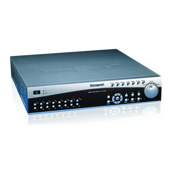
DVR for the first time, please refer to this part first. Front Panel The front panel is shown in Figure 2-1. Figure 2-1 The Front Panel of HD-16DVR-C Please refer to the following sheet for front panel button information. Name Icon Function... - Page 24 Overview and Controls Shift current activated control, Left/2 Right/3 During playback, click these buttons to control playback bar. Confirm current operation Menu/Enter Menu Go to default button Go to menu Go to previous menu, or cancel current operation. During playback, click it to restore real-time monitor mode.
-
Page 25: Rear Panel
IR Receiver Receives the signal from the remote controller. Rear Panel HD-16DVR-C rear panel is shown as below. See Figure 2-2. Figure 2-2 The Rear Panel of HD-16DVR-C Please refer to the following table for detailed information. -
Page 26: Connection Diagram
Video input DB25 port (5th to 16th-channel audio input port) Audio output Intercom input port Intercom output port Network port eSATA port (reserved, not effective for HD-16DVR-C) RS232 port USB port HDMI video output VGA video output Alarm input/alarm output/RS485 port... -
Page 27: Remote Controller
Honeywell Figure 2-3 Device Connection Remote Controller The remote controller interface is shown as in Figure 2-4. -
Page 28: Figure 2-4 Remote Controller
Overview and Controls Figure 2-4 Remote Controller Function Record search Multiple-window switch 0-9 number keys ESC, Cancel Reserved, not effective for HD-16DVR-C Confirm /menu key Direction keys Auxiliary function key Remote address switch Previous Backward playback Slow play Play/Pause Fast play... -
Page 29: Mouse Control
Honeywell Record Mouse Control The password input dialogue box will pop up if you have not logged in. In real-time monitor mode, you can go to the main menu. When you have selected one menu item, left click the mouse to view menu content. - Page 30 Overview and Controls Implement special control operation such as double click one item in the file list to playback the video. Double left In multiple-window mode, double left click one channel to view in full-window. click mouse Double left click current video again to go back to previous multiple-window mode.
-
Page 31: Installation And Connections
Honeywell 3 Installation and Connections All the installation and operations here should conform to Note your local electrical safety rules Check Unpacked DVR When you receive the DVR from the forwarding agent, please check whether there is any visible damage. The protective materials used for the package of the DVR can protect during most transportation caused accidental. - Page 32 Installation and Connections Please follow the instructions below to install the hard disk. 1. Loosen the screws and remove the 2. Line up the HDD to the four holes of the upper cover. the HDD bracket. 3. Use four screws to fix HDD. 4.
-
Page 33: Connecting Power Supply
Honeywell Connecting Power Supply Please check whether the input voltage matches device power supply rating. We recommend you use UPS to guarantee steady operation, DVR life span, and other peripheral equipments’ operation such as cameras. Connecting Video Input and Output Devices Connecting Video Input The video input interface is BNC. -
Page 34: Connecting Video Output
Installation and Connections Connecting Video Output Main video output includes BNC (CVBS PAL/NTSC, 1.0VP-P, 75Ω), VGA and HDMI. SPOT (matrix) output and loop output are also supported by BNC connection. The system supports the three kinds of outputs at the same time. 1280x720 (720p) resolution setting is recommended for HDMI output. -
Page 35: Alarm Input And Output Connection
Honeywell If the sound box and the pick-up cannot be separated spatially, it is easy to cause a squeaking noise. In this case you can adopt the following measures: Use better sound pick-up with better directing property. Reduce the volume of the sound box. -
Page 36: Alarm Input Port
Installation and Connections Figure 3-1 Alarm Input and Output Parameter Grounding Alarm Ground line Alarm Input 1-16 become valid in low voltage. 1-4 NO C: four Normal Open activation outputs. Relay Output 5 NO C NC: Normal Open – Normal Closed dual activation output Controllable +12VDC power output as the 6th alarm output Ctrl 12V... -
Page 37: Alarm Output Port
Honeywell Figure 3-2 Sample of Alarm Input (Normal Close Type) Alarm Output Port Three ways to relay alarm output (NO contact). External power supply is needed for external alarm device. To avoid overloading, please read the following relay parameters sheet carefully. -
Page 38: Rs232
Installation and Connections Between touches with same Surge voltage 1500V (10×160us) polarity Length of open time 3ms max Length of closed time 3ms max Mechanical 50×106 times (3Hz) Longevity Electrical 200×103 times (0.5Hz) Temperature +70 ℃ ℃ RS232 RS232 port is reserved for technical support diagnosis and upgrade. RS485 When the DVR receives a camera control command, it transmits that command up the coaxial cable to the PTZ device. -
Page 39: Usb
Honeywell e. The voltage between of A,B lines of the decoder should be less than 2. Connect the other end of the cable to the proper pins in the connector on the camera. 3. Please follow the instructions to configure a camera to enable each PTZ device on the DVR. -
Page 40: Overview Of Navigation And Controls
Overview of Navigation and Controls 4 Overview of Navigation and Controls Before operation, please make sure you have properly installed HDD and all the cable connections. Login, Logout & Main Menu Login After the system has booted up, default video display will be in multiple- window mode. -
Page 41: Main Menu
Honeywell Figure 4-1 Menu Login Main Menu After you have logged in, the system main menu will appear as shown below. See Figure 4-2. There are a total of six icons: search, information, setting, backup, advanced and shut down. You can move the cursor to highlight the icon, and then double-click the mouse to enter the sub-menu. -
Page 42: Auto Resume After Power Failure
Overview of Navigation and Controls One is from menu option: In the main menu, click the shut down button, and you can see an interface as shown below. See Figure 4-3. Figure 4-3 Logout Menu You have several options. See Figure 4-4. -
Page 43: Manual Record
Honeywell Manual Record Live Viewing After you have logged in, the system is in live viewing mode. You can see the system date, time and channel name. If you want to change the system date and time, you can refer to general settings (Main MenuSettingGeneral). -
Page 44: Figure 4-5 Recording Control Menu
Overview of Navigation and Controls Manual: The highest priority. After being set to manual mode, all selected channels will start regular (continuous) recording. Automatic: Channel recording follows recording schedule setting (Main MenuSettingSchedule) Closed: the channel stops recording. Figure 4-5 Recording Control Menu Enable/disable recording in specified channels Please check the current channel status: “○”... -
Page 45: Figure 4-7 Automatic Recording In All Channels
Honeywell When system is in automatic recording, all channels will be recorded as you set up in Main menuSettingSchedule. The corresponding indication light on the front panel will turn on. Figure 4-7 Automatic Recording in All Channels Manual recording in all channels Highlight “ALL”... -
Page 46: Search & Playback
Overview of Navigation and Controls Figure 4-9 Stop Recording in All Channels Search & Playback Search Menu Click the search button in the main menu, search interface is shown below. Figure 4-10. Usually there are three file types: R: Regular recording file. ... -
Page 47: Figure 4-10 Record Search Menu
Honeywell Figure 4-10 Record Search Menu Please refer to the following chart for more information. Serial Number Function Play Backward Stop Slow play Fast play Previous frame Next frame Volume Previous file Next channel Next file... -
Page 48: Basic Operation
Overview of Navigation and Controls Previous channel Search Backup Redundancy Search Basic Operation Playback There are various search modes: video type, channel number or time. The system can display a max of128 files in one screen. You can use the page up/down button to view if there are more than one page. - Page 49 Honeywell Button Illustration Remarks In playback mode, click this button to switch between various fast play Fast play button modes such as fast play 1, fast play Frame rate may 2 and more. vary due to different Slow play button ►...
-
Page 50: Calendar
Overview of Navigation and Controls rounds, you get fast backward 2. You can continue turning to get different speed. In playback, click play/pause button to pause normal playback, slowly Manual playback turn the jog (inner dial) clock-wise to frame by frame view frame by frame, counter clock wise to scan I frame. -
Page 51: Schedule
Honeywell Schedule After the system has booted up it will enter a default 24-hour regular mode. You can set the record type and time in schedule interface. Schedule Menu In the main menu, from Setting to Schedule, you can go to the schedule menu. -
Page 52: Figure 4-12 Schedule Menu
Overview of Navigation and Controls Figure 4-12 Schedule Menu Quick Setup This function allows you to copy one channel setup to another. After setting one channel, you can click the Copy button and switch to another channel and then click the Paste button. You can finish setting one channel and click the Save button to keep the setting of that channel, or you can finish the entire setup and then click the Save button to keep all of the modified settings. -
Page 53: Detect
Honeywell If current channel is recording now, the setup will get activated immediately, and the current record will be terminated and a new file is created as redundancy recording is started. After setup is completed, please click save button, system goes back to the previous menu. - Page 54 Overview of Navigation and Controls Show message: The system will send message to the local host screen to alarm you if you have enabled this function. Send email: The system can send out an email to alert you when the alarm occurs.
-
Page 55: Figure 4-13 Motion Detection Menu
Honeywell Figure 4-13 Motion Detection Menu Figure 4-14 Motion Detection Zone Setting... -
Page 56: Figure 4-15 Ptz Activation Setting
Overview of Navigation and Controls Figure 4-15 PTZ Activation Setting Figure 4-16 Armed Period Setting Figure 4-17 Business Day and Non-Business Day Setting... -
Page 57: Video Loss
Honeywell Video Loss Figure 4-13, select “Video Loss” from the type list. You can see the interface is shown in Figure 4-18. This function allows you to be informed when video loss has occurred. You can enable the alarm output channel and enable the show message function. -
Page 58: Alarm Setup And Alarm Activation
Overview of Navigation and Controls In “Detect” interface, the copy/paste function is only valid for Note the same type, which means you cannot copy a channel setup in video loss mode to camera masking mode. Figure 4-19 Menu of Camera Masking Alarm Setup and Alarm Activation Before operation, make sure you have properly connected alarm devices such as the buzzer. - Page 59 Honeywell Event type: Select local input. Network input is not effective in HD- 16DVR-C. Type: Normally open or normally closed. PTZ activation: Here you can set PTZ movement when the alarm occurs. For example, go to preset, tour& pattern when there is an alarm.
-
Page 60: Figure 4-20 Menu Of The Alarm
Overview of Navigation and Controls Figure 4-20 Menu of the Alarm Figure 4-21 PTZ Activation Settings... -
Page 61: Backup
Honeywell Figure 4-22 Period Setup Figure 4-23 Business Days and Non-Business Days Settings Backup DVR supports various backup devices such as CD-RW, DVD driver, USB backup and network download. The records can be played with PC by the Record Player contained in the CD. Here we introduce USB backup first. -
Page 62: Detect Device
Overview of Navigation and Controls Detect Device Click Backup, and you can see an interface shown in Figure 4-24. Here you can view device information. You can view the backup device name and its total space and free space. The device includes a USB burner, flash disk, SD card and portable HDD. The USB Flash Disk models listed in Appendix B are Note strongly recommended, models from other brands may not... -
Page 63: Figure 4-25 Backup Menu With Search Results
Honeywell When the system completes backup, you can see a dialogue box prompting successful backup. Figure 4-25 Backup Menu with Search Results Click Start, and the system will begin the burning process. At the same time, the Start button will change to the Stop button. You can view the remaining time and process bar at the bottom left. -
Page 64: Ptz Control And Color Setup
PTZ Control and Color Setup The operations described here are mainly based on PELCO-D protocol for Honeywell HSD-261/HSD- Note 361/HSPT-120 speed dome. For other protocols, there might be a little difference. -
Page 65: Ptz Setup
Honeywell PTZ Setup The camera video should be in the current screen. Before setup, check whether the following connections are right: PTZ and decoder connection Note Decoder address setup Decoder A (RS485 +) / B (RS485 -) line connects with DVR A/B line Boot up the DVR, and input the user name and password. -
Page 66: Figure 4-27 Ptz Setup Menu
Overview of Navigation and Controls Figure 4-27 PTZ Setup Menu After completing all the settings click Save. In the single window display (View 1) mode, right-click to open the interface shown in Figure 4-28 (by clicking Fn in the front panel or in the remote controller will cause a menu to appear with only Pan/Tilt/Zoom and Color Setting options). -
Page 67: Ptz Trace
Honeywell Here you can set the following items: Step: value ranges from 1 to 8. 8 direction arrows for PTZ position adjustment Zoom Focus Iris Click the buttons to adjust zoom, focus and iris. Some functions are not supported by some PTZ speed Note dome. -
Page 68: Preset/Tour/Pattern/Scan Operations
Overview of Navigation and Controls Function Shortcut Function Shortcut Name function function Zoom Near Focus Near │ ►│ Iris Close Open ► Preset/Tour/Pattern/Scan Operations Figure 4-29, click Set. The interface is shown as below. See Figure 4-30. Here you can set the following items: Preset ... -
Page 69: Preset Setup
Honeywell Auto pan Figure 4-31 Function Menu Preset, tour and pattern all need the value to be the control parameter. You can define it according to the speed dome’s user manual. You need to refer to your speed dome user’s manual for ... -
Page 70: Activate Preset
Overview of Navigation and Controls Figure 4-32 Preset Setup Activate Preset Figure 4-31, input the preset number in the “No.” field, and click Preset. Patrol setup (Tour Setup) Figure 4-30, click Patrol. The interface is shown in Figure 4-33. Input the preset number and add this preset to a patrol (tour). -
Page 71: Activate Patrol (Tour)
Honeywell Activate Patrol (tour) Figure 4-30, input the patrol (tour) number in the No. blank and click the patrol button. Pattern Setup Figure 4-30, click Pattern and then click “begin. The interface is shown as in Figure 4-34. Then you can go to... -
Page 72: Activate Auto Scan
Overview of Navigation and Controls Figure 4-35 Auto Scan Setup Activate Auto Scan Figure 4-31, click Auto Scan, and the system will begin to auto scan. Correspondingly, the Auto Scan button will change to the Stop button. Click Stop to terminate the scan operation. Click Page Switch again, and the system will go back to Figure 4-29. -
Page 73: Understanding Of Menu Operations And Controls
Honeywell 5 Understanding of Menu Operations and Controls Menu Tree This series DVR menu tree is shown as below. - Page 74 Understanding of Menu Operations and Controls Search (page Information HDD Info Version Online Users Setting General Encode Schedule RS232 Menu Network Alarm Detect Pan/ Tilt/Zoom Display Default Backup (page 45) Advanced HDD Management Alarm Output Abnormity Manual Record Account Auto Maintain TV Adjust Video Matrix Shutdown...
-
Page 75: Main Menu
Honeywell Main Menu After you have logged in, the system main menu will appear as shown below. See Figure 5-1. There are a total of six buttons: Search, Info, Setting, Backup, Advanced, and Shutdown. Move the cursor to highlight the icon, then double-click to enter the sub-menu. - Page 76 Understanding of Menu Operations and Controls Date separator: There are three denotations to separate the date: dot, beeline and solidus. DST: Here you can set DST time and date. Please enable DST function and then click set button. You can see an interface is shown as in Figure 5-3.
-
Page 77: Encode
Honeywell Figure 5-2 General Setup Menu Figure 5-3 DST Setup Menu (Weel) Figure 5-4 DST setup menu (Date) Encode Encode setting includes the following items. See Figure 5-5. - Page 78 Understanding of Menu Operations and Controls Note that some series do not support extra stream. Channel: Select the channel you want. Compression: System supports H.264. Resolution: System supports various resolutions, D1(4CIF)/CIF/QCIF. You can select from the dropdown list. The extra stream of each channel supports only QCIF resolution.
-
Page 79: Schedule
Honeywell Figure 5-5 Encode Menu Figure 5-6 Overlay Menu Schedule Refer to Schedule on page 35. RS232 RS232 interface is shown as follows. There are five items. See Figure 5-7. -
Page 80: Network
Understanding of Menu Operations and Controls Function: There are two modes for you to select. Console is for serial port or min-end platform to upgrade program. Adaptor is reserved for system integration or function enhancement. Baud rate: You can select proper baud rate. ... -
Page 81: Figure 5-8 Network Setup Menu
Honeywell DHCP: It is to activate auto search IP. When you enable the DHCP function, you cannot modify the IP/Subnet mask /Gateway. These values are from the DHCP function. If you have not enabled the DHCP function, IP/Subnet mask/Gateway will display as zero. You need to disable the DHCP function to view current IP information. -
Page 82: Figure 5-9 Advanced Settings
Understanding of Menu Operations and Controls Figure 5-9 Advanced Settings IP Filter IP filter interface is shown in Figure 5-10. You can add IP in the following list. The list supports a max of 64 IP addresses. Note that after you enable this function, only the IP listed below can access current DVR. -
Page 83: Figure 5-11 Pppoe Setup Menu
Honeywell After rebooting, DVR will connect to the internet automatically. The IP in the PPPoE is the DVR dynamic value. You can access this IP to visit the unit. Figure 5-11 PPPOE Setup Menu NTP Setup You need to install SNTP server (Such as Absolute Time Server) in your PC first. -
Page 84: Figure 5-12 Ntp Setup Menu
Understanding of Menu Operations and Controls Sydney GMT+10 Hawaii GMT-10 Alaska GMT-9 Pacific Time(P.T) GMT-8 American Mountain Time(M.T) GMT-7 American Central Time(C.T) GMT-6 American Eastern Time(E.T) GMT-5 Atlantic Time GMT-4 Brazil GMT-3 Middle Atlantic Time GMT-2 Figure 5-12 NTP Setup Menu DDNS Setup DDNS setup interface is shown in Figure... -
Page 85: Figure 5-13 Ddns Setup Menu
Note that the NNDS type includes: CN99 DDNS、NO-IP DDNS、Private DDNS、Dyndns DDNS and sysdns DDNS. The private DDNS function is reserved for integration, and currently is not effective on HD-16DVR-C. You need to download or buy a FTP service tool (such as Ser-U FTP SERVER) to establish FTP service. -
Page 86: Figure 5-14 Ftp Server Setup Menu
Understanding of Menu Operations and Controls Figure 5-14 FTP Server Setup Menu You can use a PC or FTP login tool to test setup. FTP://10.10.7.7 For example, you can login user ZHY to and then test whether it can modify or delete the folder or not. See Figure 5-15. -
Page 87: Figure 5-16 Ftp Setup Menu
Honeywell Figure 5-16 FTP Setup Menu Please check the box left to Enable to activate the FTP function. Here you can input the FTP server address, port and remote directory. When the remote directory is null, the system automatically creates folders according to the IP, time and channel. -
Page 88: Figure 5-17 Email Setup Menu
Understanding of Menu Operations and Controls Figure 5-17 Email Setup Menu Refer to the following table for detailed information. Parameter Function SMTP Server Input server address and then enable this function. Port Default value is 25. You can modify it if necessary. User Name The sender email account user name. -
Page 89: Alarm
Honeywell Under Windows Command Prompt, input ping smtp.google.com then press return. The displayed IP address 74.125.45.25 is the SMTP server IP address. Figure 5-18 Command Window Alarm Refer to Alarm Setup and Alarm Activation on page 42. Detect... -
Page 90: Display
Understanding of Menu Operations and Controls After completing all the setups click Save, and the system will go back to the previous menu. For a detailed setup, refer to Preset/Tour/Pattern/Scan Operations on page Figure 5-19 PTZ Setup Menu Display Display setup interface is shown as below. See Figure 5-20. -
Page 91: Figure 5-20 The Display Setup Menu
Honeywell Enable tour: Activate tour function. Interval: Input proper interval value here. The value ranges from 5-120 seconds. In tour process, you can use the mouse or click Shift to turn on the window switch function. Stands for opening switch function, stands for the closing switch function. -
Page 92: Default
Understanding of Menu Operations and Controls Figure 5-21 Channel Name Setup Menu In tour mode, you can see the following interface. On the right corner, right- click the mouse or click Shift, and you can control the tour. There are two buttons: stands for enabling window switch and stands for enabling... -
Page 93: Figure 5-23 Default Setup Menu
Honeywell Select all General Encode Schedule RS232 Network Alarm Detect Pan/tilt/zoom Display Channel name After all the setups please click the save button, the system will go back to the previous menu. -
Page 94: Advanced
Understanding of Menu Operations and Controls Advanced Select Advanced on the main window, and the interface is shown as follows. See Figure 5-24. There are seven function keys in total: HDD management, alarm output, abnormity, manual record, account, auto maintenance, TV adjust and video matrix. Figure 5-24 Advanced Menu HDD Management Here you can view and implement hard disk management. -
Page 95: Figure 5-25 Hdd Management Setup Menu
Honeywell Figure 5-25 HDD Management Setup Menu Click Alarm Set, and the interface is shown as follows. See Figure 5-26 (this interface is just like the abnormity setup). Refer to Abnormity on page for detailed information. Please check boxes to select the corresponding function. -
Page 96: Abnormity
Understanding of Menu Operations and Controls Figure 5-26 Abnormity Setup Menu Abnormity Abnormity interface is shown in Figure 5-27. Event type: There are several options for you such as disk error, no disk and etc. Alarm output: alarm activation output port (multiple choices). The 3-ch is ... -
Page 97: Alarm Output
Honeywell Figure 5-27 Sample of No Disk Abnormity Alarm Output Here you can set proper alarm output. Automatic: start the alarm output automatically according to the settings of Detection/Alarm/Abnormity. Manual: manually start the alarm output Closed: manually stop the alarm output Please select the mode of corresponding alarm output, then click OK, and the system will return to the previous menu. -
Page 98: Manual Record
Understanding of Menu Operations and Controls Figure 5-28 Alarm Output Setup Menu Manual Record Refer to Manual Record on page 27. Account Here you cam implement account management. See Figure 5-29. to see how to: Add new user Modify user ... -
Page 99: Auto Maintain
Honeywell Hidden user “default” is for system interior use only and cannot be deleted. When there is no login user, hidden user “default” automatically login. You can set some rights such as monitor capability for this user so that you can view some channels without login. -
Page 100: Tv Adjust
Understanding of Menu Operations and Controls Figure 5-30 Auto Maintain Setup Menu TV Adjust Here you can adjust the TV output setup. See Figure 5-31. Please drag slide bar to adjust each item. After all the setups please click OK, the system will return to the previous menu. -
Page 101: Information
Honeywell Figure 5-32 Video Matrix Menu Information Here you can view system information. There is a total of five items: HDD (hard disk information), BPS (data stream statistics), Log and version, and online user. See Figure 5-33. -
Page 102: Hdd Information
Understanding of Menu Operations and Controls Figure 5-33 Info Menu HDD Information Here is a list of hard disk type, total space, free space, video start time and status. See Figure 5-34. ○ means current HDD is normal. X means there is an error. - means there is no HDD. -
Page 103: Bps
Honeywell Figure 5-34 HDD Info Menu Tips: Click Fn or left click the mouse button to view the HDD record time and HDD type and time. Here you can view current video data stream (KB/s) and occupied hard disk storage (MB/h). See Figure 5-35. -
Page 104: Log
Understanding of Menu Operations and Controls Figure 5-35 BPS Display Menu Here you can view the system log file. The system lists the following information. See Figure 5-36. Log types include system operation, configuration operation, data management, alarm event, record operation, log clear and etc. Select the start time and end time, and then click Search. -
Page 105: Version
Honeywell Figure 5-36 Log Search Menu Version Here you can view some information related to this version. See Figure 5-37. Channel Alarm in Alarm out System version: Build Date ... -
Page 106: Online Users
Understanding of Menu Operations and Controls Figure 5-37 Version Menu Online Users Here you can manage online users. See Figure 5-38. You can disconnect one user or block one user if you have proper system rights. The max disconnection time during setup is 65535 seconds. -
Page 107: Shutdown
Honeywell Figure 5-38 Online Users Menu Shutdown Left click the shutdown button, the system will pop up a dialogue box for you to select. See Figure 5-39. Log out menu user: log out menu. You need to input password when ... -
Page 108: Figure 5-39 Shutdown Menu
Understanding of Menu Operations and Controls Figure 5-39 Shutdown Menu... -
Page 109: Web Client Operation
Honeywell 6 Web Client Operation There might be slight differences in the interface due to Note software update. Network Connection Before the web client operation, please check the following items: Network connection is right DVR and PC network setup is right. Please refer to network setup (main ... -
Page 110: Figure 6-1 Sample Of Ie Login
Web Client Operation Figure 6-1 Sample of IE Login Input your IP address here. A system pop up with warning information will ask you if you want to install webrec.cab control. Please click yes button. If you can’t download the ActiveX file, please modify your settings as follows. -
Page 111: Figure 6-3 Settings For Activex
Honeywell Figure 6-3 Settings for ActiveX After installation, the interface is shown as below. See Figure 6-4. Please input your user name and password. Default factory name is admin and password is admin. For security reasons, please modify your password after Note you first login. -
Page 112: Figure 6-4 Web Login Window
Web Client Operation Figure 6-4 Web Login Window After you logged in, you can see the main window. See Figure 6-7. This main window can be divided into the following sections. Section 1: There are five function buttons: configuration (see ... -
Page 113: Real-Time Monitor
Honeywell Preview window switch. System support 1/4/8/9/16-window real- time preview. Please you need to have the proper rights to implement preview operation. You cannot preview if you have no right to preview the either channel. See Figure 6-6. Figure 6-6 Preview Window Switch Menu... -
Page 114: Figure 6-9 Control Setup
Web Client Operation Figure 6-9 Control Setup 1: Digital zoom: Click this button and then left drag the mouse in the zone to zoom in. Right clicking mouse system restores original status. 2: Change show mode: resize or switch to full screen mode. ... -
Page 115: Ptz
Honeywell You can click this button to enable audio talk. Local Play Click Local Play, and the system pops up the following interface for you to select local play file. See Figure 6-11. Figure 6-11 Selection Menu of Local Play File Before PTZ operation, make sure you have properly set PTZ protocol. -
Page 116: Figure 6-12 Ptz Control Menu
Web Client Operation Figure 6-12 PTZ Control Menu You can click this icon to display or hide the PTZ control platform. Direction key and 3D positioning key Figure 6-12, there are eight direction keys. In the middle of the eight direction keys, there is a 3D intelligent positioning key. -
Page 117: Figure 6-13 Ptz Setup Menu
Honeywell Iris close Open Figure 6-12, click the PTZ setup button and you will see the following interface. See Figure 6-13. Figure 6-13 PTZ Setup Menu Auto Scan Figure 6-13, move the camera to your desired location and then rotate it to left rotation limit and click Left Limit. -
Page 118: Color
Web Client Operation Figure 6 -13, move the camera to your desired location and then input preset valu e. Click the add button, and you will have set one preset. Auto tour Figure 6-13, input the auto tour value and preset value. Click the add button, and you will have added one preset in the tour. -
Page 119: Picture Path And Record Path
Honeywell Or you can click the default button to use the system default setup. Figure 6-15 Color Setup Menu Picture Path and Record Path Click “More” in Figure 6-1 5, and you can see an interface shown in Figure 6-16. -
Page 120: Configuration
Web Client Operation Figure 6-18 Path Setup Menu (for Record) Click Reboot, and the system pops up the following dialog box. See Figure 6-19, Please click OK to reboot. Figure 6-19 Reboot Dialog If there’s an administrator (e.g. 888888) logged in DVR local menu, or web user doesn’t have device reboot Note privilege, DVR won’t be rebooted and a warning message... -
Page 121: Figure 6-20 Version Information Menu
Honeywell Figure 6-20 Version Information Menu HDD information Here you can view local storage status and network status including, free capacity and total capacity. See Figure 6-21. -
Page 122: Figure 6-21 Hdd Information Menu
Web Client Operation Figure 6-21 HDD Information Menu Here you can view system log. See Figure 6-22. -
Page 123: Figure 6-22 Log Information Menu
Honeywell Figure 6-22 Log Information Menu Click Backup, and the interface is shown in Figure 6-23. Figure 6-23 Log Backup Menu Please refer to the following sheet for log parameter information. Parameter Function Log types include: system operation, configuration Type operation, data management, alarm event, record operation, user management, log clear and file operation. -
Page 124: System Configuration
Web Client Operation Parameter Function You can click this button to delete all displayed log files. Clear Please note system does not support clear by type. Backup You can click this button to backup log files to current PC. System Configuration Please click Save to save your current setup. -
Page 125: Figure 6-25 Dst Setup Menu (Date)
Honeywell Figure 6-25 DST Setup Menu (Date) Figure 6-26 DST Setup Menu (Week) Please refer to the following table for detailed information. Parameter Function Used to modify system time. Please click Save after your System Time completed modification You can click this button to save the system time as your Sync PC PC current time. -
Page 126: Figure 6-27 Encode Menu
Web Client Operation You can select the language from the dropdown list. Device needs to reboot to get the modification activated. Language After reboot, please press F5 in IE or open a new IE window to update web client language. There are two options: stop recording or overwrite the HDD Full previous files when HDD is full. -
Page 127: Figure 6-28 Color Setting Menu
Honeywell Figure 6-28 Color Setting Menu Please refer to the following table for detailed information. Parameter Function Channel For selecting a monitor channel. Channel Name Displays current channel name. You can modify it. Compression H.264 It includes main stream, motion stream and alarm stream. - Page 128 Web Client Operation Parameter Function There are two options: VBR and CBR. Bit Rate Type Please note, you can set video quality in VBR mode only. The value ranges from 1 to 6. Level 6 is the best video Quality quality.
-
Page 129: Figure 6-29 Copy-To Menu
Honeywell Figure 6-29 Copy-To Menu Schedule Here you can set different periods for various days. The maximum is six periods in one day. See Figure 6-30. Figure 6-30 Schedule Setup Menu... -
Page 130: Figure 6-31 Date And Time Setup Menu
Web Client Operation Figure 6-31 Date and Time Setup Menu Please refer to the following sheet for detailed information. Parameter Function Channel Please select a channel first. Please input pre-record value here. System can record three to five seconds of video before Pre-record activating the record operation in the file. -
Page 131: Figure 6-32 Rs232 Setup Menu
Honeywell Parameter Function click Save. Click this button to get device latest configuration Refresh information. RS232 The RS232 interface is shown in Figure 6-32. Figure 6-32 RS232 Setup Menu Please refer to the following sheet for detailed information. Parameter Function... -
Page 132: Figure 6-33 Network Setup Menu
Web Client Operation Parameter Function Parity Multiple options: none, odd, even, etc. System default setup Function: Console. Data bit: 8 Stop bit: 1 Baud bit: 115200 Parity: None. Network The network interface is shown as in Figure 6-33. - Page 133 Honeywell Parameter Function Dynamically get IP address. You can get the device DHCP IP from the DHCP server if you enabled this function. TCP Port Default value is 37777. HTTP Port Default value is 80. Network user max amount. The value ranges from 0 to 10.
-
Page 134: Figure 6-34 Email Setup Menu
Web Client Operation Figure 6-34 Email Setup Menu Please refer to the following sheet for detailed information. Parameter Function SMTP Server Input server address and then enable this function. Port Default value is 25. You can modify it if necessary. User Name The sender email account user name. -
Page 135: Figure 6-35 Ddns Setup Menu
Honeywell Figure 6-35 DDNS Setup Menu Please refer to the following sheet for detailed information. Parameter Function You can select DDNS protocol from the dropdown list and then enable DDNS function. The private DDNS protocol Server Type means you use your self-defined private protocol to realize DDNS function. -
Page 136: Figure 6-36 Nas Setup Menu
Web Client Operation Figure 6-36 NAS Setup Menu Please refer to the following sheet for detailed information. Parameter Function Please select network storage protocol and then enable NAS enable NAS function. Server IP Input remote storage server IP address. Port Input Remote storage server-port number. -
Page 137: Figure 6-37 Ntp Setup Menu
Honeywell Parameter Function click the save button. Click this button to get device latest configuration Refresh information. The NTP interface is shown in Figure 6-37. Here you can realize network time synchronization. Please enable current function and then input server IP, port number, time zone and update interval. -
Page 138: Figure 6-38 Alarm Setup Menu
Web Client Operation Figure 6-38 Alarm Setup Menu Please refer to the following sheet for detailed information. Parameter Function It includes local alarm/network alarm. Event Type Local alarm: Device detects alarm from input port. Network: Device detects alarm from network. Select corresponding alarm channel, and check the checkbox Alarm in beside it to enable system to detect alarm signal... - Page 139 Honeywell Parameter Function alarm device when alarm occurs. System can delay the alarm output for specified time after Alarm alarm ended. The value ranges from 10 seconds to 300 Latch seconds. System auto activates current channel to record once alarm Record occurs (working with alarm activation function).
-
Page 140: Figure 6-39 The Detection Setup Menu
Web Client Operation Figure 6-39 The Detection Setup Menu Figure 6-40 The Detection Zone Setup... - Page 141 Honeywell Please refer to the following sheet for detailed information. Parameter Function There are three types: Motion detection/video loss/Camera Event Type Masking. Select channel name from the dropdown list, and check the Channel checkbox beside it to enable its motion detection function.
-
Page 142: Figure 6-41 Ptz Setup Menu
Web Client Operation If you enabled this function, the system can send out email Email to alert you when alarms occur and end. Display video in local monitor window by tour. If there are Tour record channels selected, only the record channels will be displayed in the tour. - Page 143 Honeywell Please refer to the following sheet for detailed information. Parameter Function Channel You can select monitor channel from the dropdown list. . Protocol Select the corresponding dome protocol (such as PELCOD), Set corresponding dome address. Default value is 1. Please Address note your setup here shall comply with your dome address;...
-
Page 144: Advanced
Web Client Operation Figure 6-42 Default Setup Menu Please refer to the following sheet for detailed information. Parameter Function Select All Restore the factory default settings. Export Configuration Export system configuration to the local PC. Import Configuration Import configuration from PC to the system. Advanced HDD Management HDD management includes net storage management and local storage... -
Page 145: Figure 6-43 Hdd Management Menu
Honeywell Figure 6-43 HDD Management Menu Please refer to the following sheet for detailed information. Parameter Function Format Clear data in the disk. Read/write Set current disk as read/write. Read only Set current disk as read only. Redundant Set current disk as redundant recording. -
Page 146: Figure 6-44 Alarm I/O Config Menu
Web Client Operation Figure 6-44 Alarm I/O Config Menu Please refer to the following chart for detailed information. Parameter Function Alarm out There are six alarm output channels. Schedule Start the alarm output automatically according to the (Automatic) settings of Detection/Alarm/Abnormity. Manual Manually start the alarm output. -
Page 147: Figure 6-45 Record Control Menu
Honeywell Figure 6-45 Record Control Menu Please refer to the following chart for detailed information. Parameter Function Schedule The system enables the auto record function as you set in (Auto) record schedule setup. Enable corresponding channel to record no matter what Manual period is applied in the record setup. -
Page 148: Figure 6-46 Account Management Menu
Web Client Operation Figure 6-46 Account Management Menu Auto Maintenance Here you can select auto reboot and auto delete old file intervals from the dropdown list. See Figure 6-47. -
Page 149: Figure 6-47 Auto Maintenance Menu
Honeywell Figure 6-47 Auto Maintenance Menu Abnormity The abnormity interface is shown as below. -
Page 150: Figure 6-48 Abnormity Setup Menu
Web Client Operation Figure 6-48 Abnormity Setup Menu Please refer to the following chart for detailed information. Parameter Function Possible abnormal errors include: no disk, disk no space, disk error, net error. Event Type You need to draw a circle to enable this function. The corresponding alarm activation output channel when Alarm Out alarm occurs, There are three channels. -
Page 151: Search
Honeywell Here you can set channels for the SPOT (matrix) output and the display interval. See Figure 6-49. Figure 6-49 Matrix Config Search Click Search, and you can see an interface shown in Figure 6-50. Please select record playback mode, and then select start time, end time and channel. -
Page 152: Figure 6-50 Record Search Menu
Web Client Operation Figure 6-50 Record Search Menu Select the files you want to download and then click Download, and a dialogue box will appear as shown in Figure 6-51. Then you can specify file name and path to download the files to your local PC. Figure 6-51 Record Save Menu... -
Page 153: Figure 6-52 Record Search Menu (Saving)
Honeywell Now you can see the system begins to download and the Download button changes to the Stop button. You can click it to terminate the current operation. At the bottom of the interface, there is a process bar for your reference. See Figure 6-52. - Page 154 Web Client Operation Type Parameter Function Search general record, alarm record and Record motion detection record. Alarm Search alarm record. Motion Search motion detection record. Detection Type Local Search local record. Snapshot Search snapshot file. This function is not available with current Card device.
-
Page 155: Alarm
Honeywell Play Pause Stop Slow play Fast play Figure 6-54 Playback Menu The IP address of playback device and channel number. Playback control bar Alarm Click alarm function, and you can see an interface as shown in Figure 6-55. -
Page 156: Figure 6-55 Alarm Function Menu
Web Client Operation Here you can set device alarm type and alarm sound setup. Figure 6-55 Alarm Function Menu Please refer to the following table for detailed information. Type Parameter Function Video loss System alarms when video loss occurs. System alarms when motion detection Motion detect alarm occurs, Disk full... -
Page 157: About
Honeywell Automatically pops up alarm dialogue Prompt box. System sends out alarm sound when Sound pop-up alarm occurs. You can specify as you wish. Here you can specify alarm sound file Sound Path path. About Click About, and you can view the current web client information. See Figure 6-56. -
Page 158: Un-Install Web Control
Web Client Operation Figure 6-57 Logout Interface Un-install Web Control You can use web un-install tool “uninstall webrec.bat” in the CD to un-install web control. Before un-installation, please close all web pages, Note otherwise the un-installation might result in error. -
Page 159: Faq
Honeywell 7 FAQ 1. DVR cannot boot up properly. There are the following possibilities: Input power is incorrect. Power connection is incorrect. Power switch button is damaged. Program upgrade is wrong. HDD malfunction or something is wrong with HDD ribbon. - Page 160 4. There is no video output whether it is one-channel, multiple-channel or all-channel output. There are the following possibilities: Program is incompatible. Please upgrade to the latest version. Brightness is 0. Please restore factory default setup. There is no video input signal or it is too weak. ...
- Page 161 Honeywell Program read error, bit data is too small. There is a mosaic displayed on the full screen. Please restart the DVR to solve this problem. HDD data ribbon error. HDD malfunction. DVR hardware malfunctions. 8. There is no audio when live monitoring.
- Page 162 PTZ setup is incorrect. PTZ decoder and DVR protocol is incompatible. PTZ decoder and DVR address is incompatible. When there are several decoders, please add 120 Ohm (impedance matching) between the PTZ decoder A/B cables’ farthest end to delete the reverberation. Otherwise the PTZ control is not stable.
- Page 163 Honeywell Network fluency is not good. Client-end resources are limited. There is multiple-cast group setup in DVR. This mode can result in a mosaic appearance. Usually we do not recommend this mode. There is privacy mask or channel protection setup.
- Page 164 18. Alarm signal cannot been disarmed. There are the following possibilities: Alarm setup is incorrect. Alarm output has been opened manually. Input device error or connection is incorrect. Some program versions may have this problem. Please upgrade ...
- Page 165 Honeywell 22. Cannot playback the downloaded file. There are following possibilities: There is no media player. No DirectX 8.1 or higher graphic acceleration software is installed. Please install the latest DirectX software. There is no DivX503Bundle.exe control when you play the file ...
-
Page 166: Appendix
Appendix 8 Appendix HDD Capacity Calculation Calculate total capacity needed by each DVR according to video recording (video recording type and video file storage time). 1. According to formula (1), calculate storage capacity that is the capacity of each channel needed for each hour, unit Mbyte. ... -
Page 167: Compatible Usb Drive List
Honeywell ×a% In the formula:a% means alarm occurrence rate. Compatible USB Drive List Please upgrade the DVR firmware to the latest version to Note ensure the accuracy of the table below. If you use the USB drive, please confirm the format FAT or FAT32. - Page 169 35F Tower A, City Center, 100 Zun Yi Road, Shanghai 200051, China TEL +86 21 22196888 FAX +86 21 62370740 Honeywell Security (China) Co., Ltd. Block 28, Section 2 Huai De Cui Gang Industrial Estate Fu Yong, Bao An, Shenzhen, P.R.China...
Need help?
Do you have a question about the HD-16DVR-C and is the answer not in the manual?
Questions and answers