Sign In
Upload
Manuals
Brands
ABB Manuals
Control Unit
ACS880-204LC
ABB ACS880-204LC Manuals
Manuals and User Guides for ABB ACS880-204LC. We have
1
ABB ACS880-204LC manual available for free PDF download: Hardware Manual
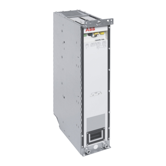
ABB ACS880-204LC Hardware Manual (278 pages)
IGBT Supply modules
Brand:
ABB
| Category:
Control Unit
| Size: 23.91 MB
Table of Contents
Table of Contents
5
Table of Contents
7
1 Introduction to the Manual
13
Contents of this Chapter
13
Applicability
13
Safety Instructions
13
Target Audience
13
Categorization by Frame Size and Option Code
14
Use of Component Designations
14
Terms and Abbreviations
14
Related Documents
15
2 Operation Principle and Hardware Description
17
Contents of this Chapter
17
Operation Principle
17
Simplified Main Circuit Diagram
18
Charging
18
Overview Diagram of the Drive System
19
Cooling System
19
Single-Line Circuit Diagrams of the Supply Unit
20
Frame 1×R8I
20
Frame R8I Multiples
21
IGBT Supply Module Hardware
22
Frame R8I Hardware
22
Module Layout
22
Coolant Connectors
23
Connectors X50
23
Fiber Optic Connectors
24
Control Interfaces
25
BCU Control Unit of Frame R8I and Multiples
25
Overview of the Control Connections of the BCU Control Unit
26
Supply Unit Control Devices
27
Main Disconnecting Device
27
Auxiliary Voltage Switch
27
Operating Switch
27
Emergency Stop and Emergency Stop Reset Buttons
27
ACX-AP-X Control Panel
27
Line-Up Charging Switch
28
Local Charging Control Switch
28
DC Switch-Disconnector
28
Charging Switch for Unit Charging
28
DC Switch-Disconnector for Line-Up Charging
28
PC Connection
29
Fieldbus Control
29
Type Designation Labels
29
Type Designation Key
30
IGBT Supply Module
30
LCL Filter
30
3 Moving and Unpacking the Module
31
Contents of this Chapter
31
4 Cabinet Construction
33
Contents of this Chapter
33
Limitation of Liability
33
Switching, Disconnecting and Protecting Solution
33
Frame R8I
33
Cabinet Temperature Supervision
34
Installation Examples
35
BLCL-15LC-7 / BLCL-24LC-7 in a 600 MM Wide Rittal VX25 Enclosure
36
Layout Drawing
36
Pipe Routing Example (BLCL-15LC-7)
37
Pipe Routing Example (BLCL-24LC-7 and BLCL-25LC-7)
37
Installation Stages
38
Overview of Kits
39
Stage 1: Installation of Common Parts
40
Stage 2: Installation of LCL Side Plates and Common AC Bus
41
Stage 3: Installation of Brackets for Flat-PLS Holder
42
Stage 4A: BLCL-15LC-7: AC Connection and Fuse Busbars Installation
43
Stage 4B: BLCL-24LC-7: AC Connection and Fuse Busbars Installation
44
Stage 5: Installation of LCL Choke Mounting Mechanics and LCL ISU Connection
45
Stage 6: LCL Choke and LCL Choke Busbar Installation
46
Stage 7: Heat Exchanger, Heat Exchanger Mechanics and Cooling Components
47
Installation
47
Stage 8A: BLCL-15LC-7: LCL Capacitor Support, Fan Support Mechanics and Fan Installation
48
Stage 8B: BLCL-24LC-7: LCL Capacitor Support, Fan Support Mechanics and Fan Installation
49
Stage 9: Installation of LCL Shroud Kit
50
BLCL-25LC-7 in a 600 MM Wide Rittal VX25 Enclosure
51
Installation Stages
51
Overview of Kits
52
Stage 1: Installation of Common Parts
53
Stage 2: Installation of LCL Side Plates and Common AC Bus
54
Stage 3: Installation of Brackets for Flat-PLS Holder
55
Stage 4: AC Connection and Fuse Busbars Installation
56
Stage 5: Installation of LCL Choke Mounting Mechanics and LCL ISU Connection
57
Stage 6: LCL Choke and LCL Choke Busbar Installation
58
Stage 7: Heat Exchanger, Heat Exchanger Mechanics and Cooling Components
59
Installation
59
Stage 8: LCL Capacitor Support, Fan Support Mechanics and Fan Installation
60
Stage 9: Installation of LCL Shroud Kit
61
One R8I Module in a 400 MM Wide Rittal VX25 Enclosure
62
Layout Drawing
62
Pipe Routing Example
63
Installation Stages
64
Overview of Kits
65
Stage 1: Installation of Common Parts
66
Stage 2: Side Plate, Module Mounting Mechanics and Quick Connectors
67
Stage 3: Flat-PLS Support Kit for AC and Common AC Connection Busbars
68
Stage 4: Fan, Heat Exchanger and Cooling Components
69
Stage 5A: Installation of DC Busbars
70
Stage 5B: Installation of DC Switch, DC Connection and Common Mode Filter Busbar Kits
71
Stage 6: Module Installation
72
Stage 7: Installation of Shrouding
73
Two R8I Modules in a 600 MM Wide Rittal VX25 Enclosure
74
Layout Drawing
74
Pipe Routing Example
75
Installation Stages
76
Overview of Kits
77
Stage 1: Installation of Common Parts
78
Stage 2: Side Plate, Module Mounting Mechanics and Quick Connectors
79
Stage 3: Flat-PLS Support Kit for AC and Common AC Connection Busbars
80
Stage 4: Fan, Heat Exchanger and Cooling Components
81
Stage 5A: Installation of DC Busbars
82
Stage 5B: Installation of DC Switch, DC Connection and Common Mode Filter Busbar Kits
83
Stage 6: Module Installation
84
Stage 7: Installation of Shrouding
85
Three R8I Modules in a 800 MM Wide Rittal VX25 Enclosure
86
Layout Drawing
86
Pipe Routing Example
87
Installation Stages
88
Overview of Kits
89
Stage 1: Installation of Common Parts
90
Stage 2: Side Plate, Module Mounting Mechanics and Quick Connectors
91
Stage 3: Flat-PLS Support Kit for AC and Common AC Connection Busbars
92
Stage 4: Fan, Heat Exchanger and Cooling Components
93
Stage 5A: Installation of DC Busbars
94
Stage 5B: Installation of DC Switch, DC Connection and Common Mode Filter Busbar Kits
95
Stage 6: Module Installation
96
Stage 7: Installation of Shrouding
97
5 Electrical Installation
99
Contents of this Chapter
99
Safety and Liability
99
Electrical Safety Precautions
100
Isolation from AC Supply Networks
101
Isolation from Common DC Bus
102
General Notes
102
Printed Circuit Boards
102
Optical Components
102
Checking the Insulation of the Assembly
103
Checking the Insulation of the Input Cable
103
Checking the Compatibility with IT (Ungrounded) Systems
103
Connecting the Input Power Cables/Busbars
104
Connection Diagram
104
Connection Procedure for Power Connections Inside the IGBT Supply Module Cubicle
105
Connection Procedure
106
Connecting the LCL Filter
108
Main Breaker / Contactor
109
Installing the Charging Circuit
109
Connecting the External Power Supply Cable for the Auxiliary Circuit
109
Connecting the Control Cables
110
Connection Diagram
110
Connection Procedure
110
Connectors X50
111
Connecting a PC
112
Installing Optional Modules
113
Installing and Using CIO-01 I/O Module
113
6 Installation Checklist of the Drive
115
Contents of this Chapter
115
Checklist
115
7 Start-Up
117
Contents of this Chapter
117
Start-Up Procedure
118
Switching the Supply Unit off
120
Additional Instructions for Closing the DC Switch-Disconnector
120
8 Maintenance
121
Contents of this Chapter
121
Maintenance Intervals
121
Maintenance Timers and Counters
123
Cooling System
123
Cabinet
123
Cleaning the Interior of the Cabinet
123
Power Connections
124
Retightening the Power Connections
124
Cooling Fans
124
Replacing the Cooling Fan of the IGBT Supply Module (Frame R8I)
124
Replacing the Cooling Fan of the LCL Filter
126
IGBT Supply Module
127
Replacing the IGBT Supply Module (Frame R8I)
127
Removing the Module
127
Reinstalling the Module
129
Capacitors
130
Reforming the Capacitors
130
Control Panel
130
Cleaning the Control Panel
130
Replacing the Control Panel Battery
130
Control Unit
130
Replacing the Memory Unit
130
Replacing the BCU Control Unit Battery
131
Leds and Other Status Indicators
131
Control Panel and Panel Platform/Holder Leds
131
R8I Module Leds
132
9 Ordering Information
133
Contents of this Chapter
133
Kit Code Key
134
Frame R8I and Multiples
135
IGBT Supply Modules
135
LCL Filters
136
Control Panel
137
Control Electronics
138
Control Unit
138
Fiber Optic Cables
138
Auxiliary Measurement Unit (BAMU)
138
CIO-01 I/O Module
139
Mechanical Installation Accessories
139
Adapter Kit (for Rittal VX25 Enclosures)
139
Module Top/Bottom Guides
140
Shrouding
141
Marine Support Kit for LCL Filters
142
AC-Side Components
142
Main Circuit Breakers and Wagons
142
IEC Busbar Shim Kits
150
Main Circuit Breaker and Wagon Cover
150
AC Fuses
151
AC-DC Charging Kits for Line-Up Charging
152
AC Busbars for LCL Filters
153
LCL Fuse Busbars
153
LCL Choke Installation Kits
154
LCL Capacitor Installation Kits
156
LCL ISU Connection Kits
157
AC Busbars
157
Quick Connector
158
DC-Side Components
158
DC Bus Installation Parts (for Rittal VX25 Enclosures)
158
DC Connection Parts 1 of 2 (for Rittal VX25 Enclosures)
159
DC Fuses
160
DC Switch-Disconnector Kits for Unit Charging
161
DC Charging Kits for Unit Charging (for Units with DC Switch-Disconnector)
162
Charging Resistors or Unit Charging (for Units with DC Switch-Disconnector)
162
DC Switch-Disconnector for Line-Up Charging
162
DC Connection Parts 2 of 2 (for Rittal VX25 Enclosures)
163
Flat-PLS Busbars (Common DC) for LCL Filters
163
Charging Mechanics
164
DC Connection Charging Mechanics
164
Common Mode Filter Busbars
165
Common Mode Filters
165
Cooling System Parts
165
Coolant Distribution Manifold Kits
165
Piping
167
Heat Exchanger
168
Cooling System Parts for LCL Filters
168
Cooling Fans for LCL Filters
169
Cooling Fans for IGBT Supply Modules
170
10 Internal Cooling Circuit
171
Contents of this Chapter
171
Applicability
171
Internal Cooling System
171
Connection to a Cooling Unit
173
Connection to an ACS880-1007LC Cooling Unit
173
Connection to a Custom Cooling Unit
173
General Requirements
173
Coolant Temperature Control
173
Filling up and Bleeding the Internal Cooling Circuit
174
Drive Line-Ups with an ACS880-1007LC Cooling Unit
174
Drive Line-Ups with a Custom Cooling Unit
174
Draining the Internal Cooling Circuit
176
Maintenance Intervals
176
Technical Data
176
Coolant Specification
176
Coolant Type
176
Temperature Limits
176
Pressure Limits
178
Coolant Flow Rate Limits
178
Cooling Circuit Materials
178
11 Technical Data
181
Contents of this Chapter
181
Ratings
182
Definitions
182
Derating
183
Ambient Temperature Derating
183
Altitude Derating
183
Type Equivalence Table
183
Fuses
184
LCL Filters
184
Kit Contents
184
Technical Data
185
Charging Kit Contents
185
Dimensions and Weights
185
Free Space Requirements
185
Allowable Mounting Orientations
185
Losses, Cooling Data and Noise
186
Tightening Torques
188
Electrical Connections
188
Mechanical Connections
188
Insulation Supports
188
Cable Lugs
188
Typical Power Cable Sizes
189
Electrical Power Network Specification
191
Control Unit Connection Data
191
Coolant Connections
191
Efficiency
191
Protection Classes
191
Optical Components
192
Ambient Conditions
193
Cooling
194
Materials
194
Internal Cooling Circuit
194
Auxiliary Circuit Current Consumption
195
Control Equipment
195
Cooling Fans
195
Definitions
195
Standards and Markings
195
Disclaimers
196
Generic Disclaimer
196
Cybersecurity Disclaimer
196
12 Control Units of the Drive
197
Contents of this Chapter
197
General
197
BCU-X2 Control Unit Layout and Connections
198
Default I/O Diagram of the Supply Control Unit
200
External Power Supply for the Control Unit (XPOW)
201
The XD2D Connector
201
The X485 Connector
202
Safe Torque off (XSTO, XSTO OUT)
202
FSO-XX Safety Functions Module Connection (X12)
202
SDHC Memory Card Slot
202
Connector Data
203
BCU-X2 Ground Isolation Diagram
205
13 Dimension Drawings
207
Contents of this Chapter
207
Frame R8I Module
208
Quick Connector
209
LCL Filter Components
210
Grid-Side Choke (BLCL-15LC-7 and BLCL-24LC-7)
210
Grid-Side Choke (BLCL-25LC-7)
211
Converter-Side Choke (BLCL-15LC-7 and BLCL-24LC-7)
212
Converter-Side Choke (BLCL-25LC-7)
213
Capacitor
214
Control Electronics
215
BCU Control Unit
215
DPMP-01 Door Mounting Kit
216
Main Circuit Breaker
217
E2.2S-A (Iec/Ul/Csa)
217
E4.2S-A (Iec/Ul/Csa)
218
AC Fuses
219
Fuses of Type 170M64Xx
219
Fuses of Type 170M70Xx
219
DC Fuses
220
14 Example Circuit Diagrams
221
Contents of this Chapter
221
Contents of Example Circuit Diagrams
221
ACS880-204LC IGBT Supply Unit 2×R8I (3AXD10000695767)
221
ACS880-204LC IGBT Supply Unit 4×R8I (3AXD10000695768)
222
Frame 2×R8I
223
Frame 4×R8I
247
Advertisement
Advertisement
Related Products
ABB ACS880-04F
ABB ACS880-304 +A003 Series
ABB ACS801
ABB ACS811
ABB ACS831
ABB ACS802
ABB ACS804
ABB ACS810-04
ABB ACS104
ABB ACSM1-204
ABB Categories
Industrial Equipment
Controller
Measuring Instruments
Battery Charger
DC Drives
More ABB Manuals
Login
Sign In
OR
Sign in with Facebook
Sign in with Google
Upload manual
Upload from disk
Upload from URL